Exhibitor - Tokistar Lighting
advertisement

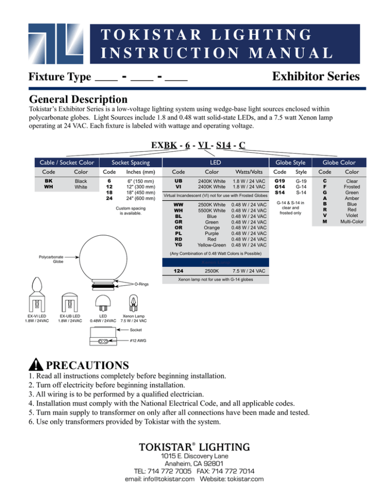
Fixture Type T O K I S TA R L I G H T I N G INSTRUCTION MANUAL Exhibitor Series - General Description Tokistar’s Exhibitor Series is a low-voltage lighting system using wedge-base light sources enclosed within polycarbonate globes. Light Sources include 1.8 and 0.48 watt solid-state LEDs, and a 7.5 watt Xenon lamp operating at 24 VAC. Each fixture is labeled with wattage and operating voltage. EXBK - 6 - VI - S14 - C Cable / Socket Color Socket Spacing LED Globe Style Globe Color Code Color Code Inches (mm) Code Color Watts/Volts Code Style Code Color BK WH Black White 6 12 18 24 6" (150 mm) 12" (300 mm) 18" (450 mm) 24" (600 mm) UB VI 2400K White 2400K White 1.8 W / 24 VAC 1.8 W / 24 VAC G19 G14 S14 G-19 G-14 S-14 C F G A B R V M Clear Frosted Green Amber Blue Red Violet Multi-Color Custom spacing is available. Virtual Incandescent (VI) not for use with Frosted Globes WW WH BL GR OR PL RD YG G-14 & S-14 in clear and frosted only Xenon Lamp 124 O-Rings EX-UB LED 1.8W / 24VAC 0.48 W / 24 VAC 0.48 W / 24 VAC 0.48 W / 24 VAC 0.48 W / 24 VAC 0.48 W / 24 VAC 0.48 W / 24 VAC 0.48 W / 24 VAC 0.48 W / 24 VAC (Any Combination of 0.48 Watt Colors is Possible) Polycarbonate Globe EX-VI LED 1.8W / 24VAC 2500K White 5500K White Blue Green Orange Purple Red Yellow-Green LED 0.48W / 24VAC 2500K 7.5 W / 24 VAC Xenon lamp not for use with G-14 globes Xenon Lamp 7.5 W / 24 VAC Socket #12 AWG PRECAUTIONS 1. Read all instructions completely before beginning installation. 2. Turn off electricity before beginning installation. 3. All wiring is to be performed by a qualified electrician. 4. Installation must comply with the National Electrical Code, and all applicable codes. 5. Turn main supply to transformer on only after all connections have been made and tested. 6. Use only transformers provided by Tokistar with the system. TOKISTAR® LIGHTING 1015 E. Discovery Lane Anaheim, CA 92801 TEL: 714 772 7005 FAX: 714 772 7014 email: info@tokistar.com Website: tokistar.com Exhibitor Instructions Page 2 Option 1 - Mounting Fixtures to Wire Rope Part#: EX-MDA-WH (White) / EX-MDA-BK (Black) Our wire rope adaptors securely holds each Exhibitor socket in place to 1/16" or 1/8"ø wire rope. Mounting Adapter 1/16" or 1/8"ø wire rope Mounting Disk Option 2 - Surface Mounting with Disks Part#: EX-MD-WH (White) / EX-MD-BK (Black) Mounting disks can be screwed in place to a variety of surfaces. Make certain the disks are properly aligned to achieve the desired effect. Attach with screws Mounting Disk Exhibitor fixture snaps directly into the Mounting Disk and locks in place. Option 3 - Surface Mounting with Straps Part#: EX-MS-WH (White) / EX-MS-BK (Black) Mounting straps can also be used to secure fixtures. Two straps are required per socket. Attach with screws Mounting Strap End Caps - Part#: ECD-WH (White) / ECD-BK (Black) Exhibitor fixtures are supplied with factory sealed end caps on the end of each run. If it is necessary to trim a fixture, a new end cap must be sealed on the end of the conductor cable with a permanently-bonding adhesive such as silicone. PRECAUTIONS Exhibitor sockets are permanently affixed to the cable. Do Not Modify Socket Spacing. At no time should the system be operated without the globes in place. Exhibitor Instructions Page 3 Transformer Instructions Transformer Location The maximum recommended distance between the fixture and the transformer varies, based upon the load of each fixture and the size of secondary wire feeding the fixture. It is impossible to give a definitive distance without considering all the variables. Electrical engineers and contractors can calculate these distances. Should you need guidance, consult the factory. Transformers with multiple outputs can be centrally located and feed fixtures in either direction. Transformer Do not exceed maximum fixture length Input Voltage Wet Location Listed Do not exceed transformer output rating Secondary Circuit Limitation To minimize voltage drop and keep conductors safely within their limitations, do not exceed the maximum lengths shown for each independent fixture. Conforming to these lengths will ensure no fixture exceeds 20 Amps (480 watts @ 24 volts). Maximum Run Lengths Socket Spacing 6" (150 mm) 12" (300 mm) 18" (450 mm) 24" (600 mm) LEDs UB & VI LEDs Xenon Lamp 0.48 Watt / 24VAC 250' (76 M) 350' (106 M) 420' (128 M) 500' (152 M) 1.8 Watt / 24VAC 125' (38 M) 200' (60 M) 225' (68 M) 250' (76 M) 7.5 Watt / 24VAC 32' (10 M) 56' (17 M) 72' (22 M) 80' (24 M) Secondary Circuit Protection Transformers are provided with circuit breakers to protect secondary circuits. The maximum size circuit breaker on a transformer is 25 amps, but the circuit wired to the breaker MUST NOT EXCEED 20 AMPS. There are several transformer sizes available, and different size breakers installed in them. For applications with multiple output transformers the total load should not exceed the breakers rating, and the total combined load of all outputs should not exceed the transformers rating. PRECAUTIONS Transformers should be installed in an accessible location. Magnetic transformers generate heat and must be installed in locations where there is free-air circulation. For additional information, please refer to the instruction manual provided with your transformer. TOKISTAR® LIGHTING 1015 E. Discovery Lane Anaheim, CA 92801 TEL: 714 772 7005 FAX: 714 772 7014 email: info@tokistar.com Website: tokistar.com Version 1.1

