Dashmount Installation Instruction
For 250-3592 and 250-3593 Applications
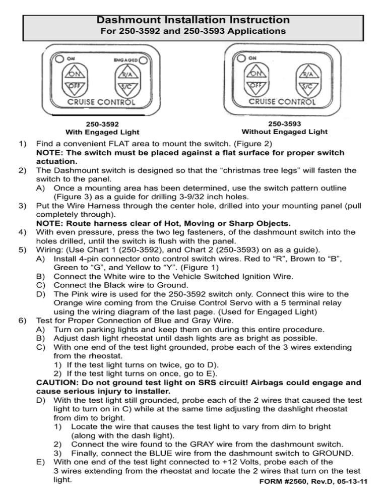
250-3592
With Engaged Light
1)
2)
3)
4)
5)
6)
250-3593
Without Engaged Light
Find a convenient FLAT area to mount the switch. (Figure 2)
NOTE: The switch must be placed against a flat surface for proper switch
actuation.
The Dashmount switch is designed so that the “christmas tree legs” will fasten the
switch to the panel.
A) Once a mounting area has been determined, use the switch pattern outline
(Figure 3) as a guide for drilling 3-9/32 inch holes.
Put the Wire Harness through the center hole, drilled into your mounting panel (pull
completely through).
NOTE: Route harness clear of Hot, Moving or Sharp Objects.
With even pressure, press the two leg fasteners, of the dashmount switch into the
holes drilled, until the switch is flush with the panel.
Wiring: (Use Chart 1 (250-3592), and Chart 2 (250-3593) on as a guide).
A) Install 4-pin connector onto control switch wires. Red to “R”, Brown to “B”,
Green to “G”, and Yellow to “Y”. (Figure 1)
B) Connect the White wire to the Vehicle Switched Ignition Wire.
C) Connect the Black wire to Ground.
D) The Pink wire is used for the 250-3592 switch only. Connect this wire to the
Orange wire coming from the Cruise Control Servo with a 5 terminal relay
using the wiring diagram of the last page. (Used for Engaged Light)
Test for Proper Connection of Blue and Gray Wire.
A) Turn on parking lights and keep them on during this entire procedure.
B) Adjust dash light rheostat until dash lights are as bright as possible.
C) With one end of the test light grounded, probe each of the 3 wires extending
from the rheostat.
1) If the test light turns on twice, go to D).
2) If the test light turns on once, go to E).
CAUTION: Do not ground test light on SRS circuit! Airbags could engage and
cause serious injury to installer.
D) With the test light still grounded, probe each of the 2 wires that caused the test
light to turn on in C) while at the same time adjusting the dashlight rheostat
from dim to bright.
1) Locate the wire that causes the test light to vary from dim to bright
(along with the dash light).
2) Connect the wire found to the GRAY wire from the dashmount switch.
3) Finally, connect the BLUE wire from the dashmount switch to GROUND.
E) With one end of the test light connected to +12 Volts, probe each of the
3 wires extending from the rheostat and locate the 2 wires that turn on the test
light.
FORM #2560, Rev.D, 05-13-11
CAUTION: Do not use SRS circuit for +12 Volts! Airbags could engage and
cause serious injury to installer.
1) With the test light still at +12 Volts, probe each of these 2 wires while at the
same time adjusting the dashlight rheostat from dim to bright.
2) Locate the wire that causes the test light to vary from dim to bright (along
with the dash light).
3) Connect this wire to the Blue wire that extends from the dashmount switch.
4) Finally, connect the GRAY wire to +12 Volts.
Test Configuration
For C) and D)
Test Configuration
For E)
RHEOSTAT
RHEOSTAT
Chart 1
For 250-3592 Applications
COLOR WIRE
FUNCTION
CONNECTIONS
Red
Control Switch
To 4-pin Connector “R”
Brown
Control Switch
To 4-pin Connector “B”
Yellow
Control Switch
To 4-pin Connector “Y”
Green
Control Switch
To 4-pin Connector “G”
Black
Ground
To Ground
White
Ignition
To Switched Ignition
Gray
Back Light
*See Step 6 on page 1
Pink (1176)
Engaged Light
To Servo
Dk. Green (1199)
Engaged Light
To Actuator
Blue
Back Light
*See Step 6 on page 1
Page 2
Chart 2
For 250-3593 Applications
COLOR WIRE
FUNCTION
CONNECTIONS
Red
Control Switch
To 4-pin Connector “R”
Brown
Control Switch
To 4-pin Connector “B”
Yellow
Control Switch
To 4-pin Connector “Y”
Green
Control Switch
To 4-pin Connector “G”
Black
Ground
To Ground
White
Ignition
To Switched Ignition
Gray
Back Light
*See Step 6 on page 1
Pink (1176)
Not Used For This Application (Cut and Tape)
Blue
Back Light
*See Step 6 on page 1
Control Switch Connections
Figure 1
Dashmount Switch Mounting
Figure 2
Page 3
Figure 3
Wiring Diagram for Engagemnet Light Feature of 250-3592
5 Terminal Relay
86
Ignition
Pink Wire At Switch
87
87A
Not Used
30
Orange Wire From
Cruise Module
85
Ignition
ROSTRA PRECISION CONTROLS, INC 1996
ALL RIGHTS RESERVED
PRINTED IN THE USA


