LEP 4.3.05 Magnetic field outside a straight conductor
advertisement

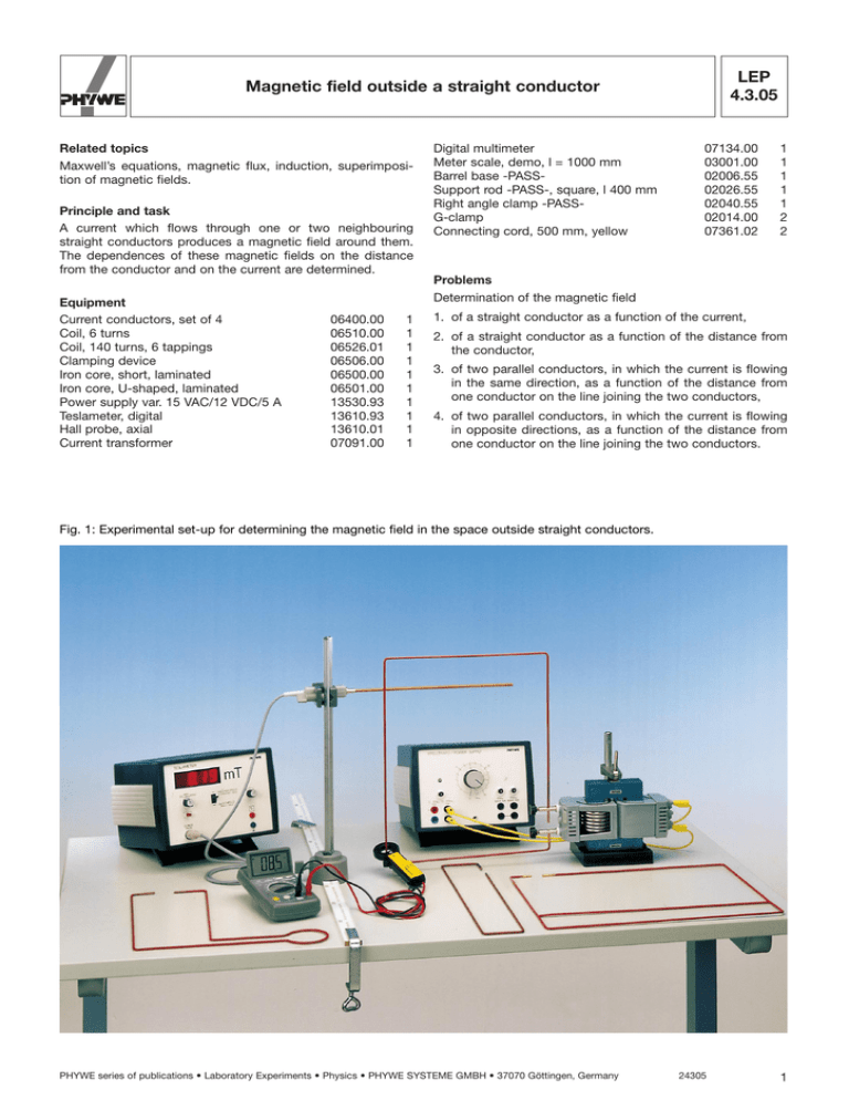
R LEP 4.3.05 Magnetic field outside a straight conductor Related topics Maxwell’s equations, magnetic flux, induction, superimposition of magnetic fields. Principle and task A current which flows through one or two neighbouring straight conductors produces a magnetic field around them. The dependences of these magnetic fields on the distance from the conductor and on the current are determined. Equipment Current conductors, set of 4 Coil, 6 turns Coil, 140 turns, 6 tappings Clamping device Iron core, short, laminated Iron core, U-shaped, laminated Power supply var. 15 VAC/12 VDC/5 A Teslameter, digital Hall probe, axial Current transformer Digital multimeter Meter scale, demo, l = 1000 mm Barrel base -PASSSupport rod -PASS-, square, l 400 mm Right angle clamp -PASSG-clamp Connecting cord, 500 mm, yellow 07134.00 03001.00 02006.55 02026.55 02040.55 02014.00 07361.02 1 1 1 1 1 2 2 Problems Determination of the magnetic field 06400.00 06510.00 06526.01 06506.00 06500.00 06501.00 13530.93 13610.93 13610.01 07091.00 1 1 1 1 1 1 1 1 1 1 1. of a straight conductor as a function of the current, 2. of a straight conductor as a function of the distance from the conductor, 3. of two parallel conductors, in which the current is flowing in the same direction, as a function of the distance from one conductor on the line joining the two conductors, 4. of two parallel conductors, in which the current is flowing in opposite directions, as a function of the distance from one conductor on the line joining the two conductors. Fig. 1: Experimental set-up for determining the magnetic field in the space outside straight conductors. PHYWE series of publications • Laboratory Experiments • Physics • PHYWE SYSTEME GMBH • 37070 Göttingen, Germany 24305 1 R LEP 4.3.05 Magnetic field outside a straight conductor Set-up and procedure The experimental set-up is arranged as shown in Fig. 1. The current transformer is used to measure the secondary current (20 A - 120 A). Since the primary and secondary current have a linear relationship, the primary current can also be measured. However, a calibration curve for primary/secondary current should then be recorded for each conductor. Because of the heating of the conductors, the current must be readjusted of a “warm-up time” must be allowed to elapse. A phase displacement can occur between the “construction-kit” transformer and the magnetic field meter, giving the illusion of a “negative” magnetic field (minimum of the magnetic field indicator with increasing current). This can be eliminated by reversing the polarity of the primary of the transformer. Higher short-time secondary currents can be achieved by connecting the constant and variable voltage in series on the power unit. Attention should be paid to the correct phase angle. Fig. 2: Contribution of a conductor section dl to the magnetic field at point Q. Theory and evaluation R Maxwell’s 1st equation for the case when electric fields E , variable with time, are absent, R R R R r B · ds = µo e j · da C A (1) From the regression line to the measured values of Fig. 3 with the exponential statement Y = A · XB together with Maxwell’s 4th equation R the exponent R e B · da = o, A (2) B = 0.97 ± 0.01 provides the relationship between the steady electric current I flowing through the area A R and the slope A = 52.91 ± 0.01 A /mT R I = e j · da A with (3) this gives µo = 1.3 · 10–6 and the magnetic field B which it produces. C is the boundary of A. A’ is any given enclosed area. R ist the electrical current density. j ist the magnetic field constant, µo µo = 1.26 · 10–6 (see (3)) Vs . Am Vs . Am From (1) and (2) one obtains, for a long straight conductor R *B * = µo I · 2p * R r* (3) R where r is the distance of the conductor from the point at which the magnetic R field is measured. R R The direction of B is * both to r and to j · For a finite conductor one obtains, with the notation of Fig. 2: R dB = 1 I R R µ dl 3 r ’ 4p o r 3 (Biot-Savart) and from this µ I *B * = o (cos f1 – cos f2). 4p r R 2 24305 Fig. 3: Relationship between current value and magnetic field of a long conductor (distance between conductor and measuring point: 1.1 cm). PHYWE series of publications • Laboratory Experiments • Physics • PHYWE SYSTEME GMBH • 37070 Göttingen, Germany R LEP 4.3.05 Magnetic field outside a straight conductor Fig. 4: Magnetic field of a long conductor as a function of distance ( I = 100 A). Fig. 6: Magnetic field component By of two parallel conductors on the x-axis as a function of the distance from one conductor, if the current in both conductors is in the same direction. Because of the small zero-deflection due to the instrument and the effect of the other conductor and the “constructionkit” transformer, it is appropriate to carry out the measurement with small distances (up to approx. 3 cm) and with large currents (approx. 100 A). For the case of two parallel conductors in the z-direction, both carrying the same current I in the same direction (p = 1) or in opposite directions (p = –1), the superimposition of the magnetic fields gives the components Bx and By of the magnetic field at point Q with the notation of Fig. 5. R R Bx = *B1* sina1 + p · *B2* sina2 = = µo I (sin2a1 + p · sin2a2) 2p · s R R By = *B1* cosa1 + p · *B2* cosa2 = = µo I 1 1 ( · cos2a1 + p · · cos2a2) 2p b+d b For Q on the x-axis, one obtains (a1 = a2 = o) µ I 1 1 By = o ( + p· ). 2p b+d b The peak at the minimum of the magnetic field originates from the reflection of the negative magnetic field as positive values, since the measuring instrument only indicates the absolute value of the magnetic field. The different values of the magnetic field at r = –5 mm and r = +5 mm occur because of the additive or subtractive superimposition of the magnetic fields of conductors 1 and 2. Fig. 5: Magnetic field of two conductors 1 and 2. The increase in the field at conductor 2 in comparison with conductor 1 at r = 65 mm as compared with r = 5 mm occurs because of the higher current density in conductor 2, which results from the resistance of the connecting piece between conductors 1 and 2. Finally, beyond conductor 2 (r = 75 mm), the effect of conductor 3 becomes noticeable. This is parallel to conductors 1 and 2, but the current in it flows in the opposite direction to that in conductors 1 and 2 and thus reinforces the magnetic field of 1 and 2 in this area. PHYWE series of publications • Laboratory Experiments • Physics • PHYWE SYSTEME GMBH • 37070 Göttingen, Germany 24305 3 R LEP 4.3.05 Magnetic field outside a straight conductor Fig. 7: Magnetic field component By of two parallel conductors on the x-axis as a function of the distance from one conductor, if the current in the two conductors is in opposite directions ( I = 107 A). The strengthening of the fields can be clearly seen in the space between the two conductors, compared with the reduction in the area beyond the two conductors. 4 24305 PHYWE series of publications • Laboratory Experiments • Physics • PHYWE SYSTEME GMBH • 37070 Göttingen, Germany


