Lecture 5
advertisement

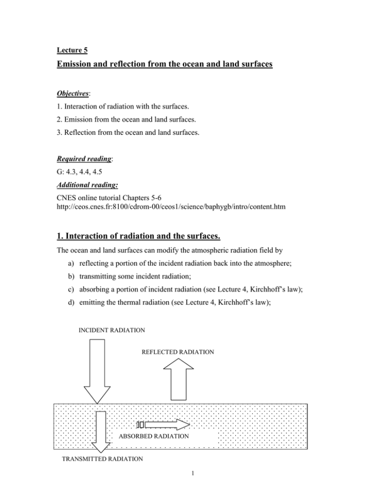
Lecture 5 Emission and reflection from the ocean and land surfaces Objectives: 1. Interaction of radiation with the surfaces. 2. Emission from the ocean and land surfaces. 3. Reflection from the ocean and land surfaces. Required reading: G: 4.3, 4.4, 4.5 Additional reading: CNES online tutorial Chapters 5-6 http://ceos.cnes.fr:8100/cdrom-00/ceos1/science/baphygb/intro/content.htm 1. Interaction of radiation and the surfaces. The ocean and land surfaces can modify the atmospheric radiation field by a) reflecting a portion of the incident radiation back into the atmosphere; b) transmitting some incident radiation; c) absorbing a portion of incident radiation (see Lecture 4, Kirchhoff’s law); d) emitting the thermal radiation (see Lecture 4, Kirchhoff’s law); INCIDENT RADIATION REFLECTED RADIATION ABSORBED RADIATION RANSMITTED RADIATION TRANSMITTED RADIATION 1 Conservation of energy requires that monochromatic radiation incident upon any surface, Ii, is either reflected, Ir, absorbed, Ia, or transmitted, It . Thus Ii = Ir + Ia + It 1 = Ir / Ii + Ia / Ii + It / Ii = R + A+ T [5.1] [5.2] where T is the transmission, A is the absorption, and R is the reflection of the surface. In general, T, A, and R are a function of the wavelength: Rλ + Aλ+ Tλ =1 [5.3] Blackbody surfaces (no reflection) and surfaces in LTE (from Kirchhoff’s law): Aλ = ελ [5.4] Opaque surfaces (no transmission): Rλ + Aλ = 1 [5.5] ελ = 1- Rλ [5.6] Thus for the opaque surfaces 2. Emission from the ocean and land surfaces. Emissivity of the surfaces: • In general, emissivity depends on the direction of emission, surface temperature, wavelength and some physical properties of the surface • In the thermal IR (4µm<λ< 100µm), nearly all surfaces are efficient emitters with the emissivity > 0.8 and their emissivity does not depend on the direction. Therefore, the intensity emitted from a unit surface area at a given wavelength is Iλ = ελ Bλ(Ts) • In the shortwave region (0.1 µm <λ< 4 µm), emissivity is negligibly small. • In microwave (0.1 cm<λ< 100 cm), emissivity depends on the type and state of the surface. NOTE: Differences in the emissivity of ice vs. water provide the basis for microwave remote sensing of sea-ice (see Lab 3) 2 Table 5.1 Emissivity of some surfaces in the IR region from 10 to12 µm. Surface Water Ice Green grass Sand Snow Granite Emissivity 0.993-0.998 0.98 0.975-0.986 0.949-0.962 0.969-0.997 0.898 Figure 5.1 Examples of IR spectral emissivity of some surfaces. 3 Figure 5.2 Examples of spectral emissivity of some surfaces in the microwave. 2. Reflection from surfaces. Bi-directional reflectance distribution function (BRDF) is introduced to characterize the angular dependence in the surface reflection and defined as the ratio of the reflected intensity (radiance) to the radiation flux (irradiance) in the incident beam: R ( µ r ,ϕ r , µ i ,ϕ i ) = π dI ↑ ( µ r , ϕ r ) I ↓ ( µ i ,ϕ i ) µ i dΩ i [5.7] where µ i = cos( θ i ) and θi is the incident zenith angle, ϕi is the incident azimuthal angle, and µ r = cos( θ r ) and θr is the viewing zenith angle, ϕr is the viewing azimuthal angle. 4 Depending on a surface, BRDF has a specific dependence on the wavelength. It plays a central role in the remote sensing of planetary surfaces. Figure 5.3 Examples of BRDF of red (diamonds) and near-IR (squares) POLDER channels. POLDER (Polarization and Directionality of the Earth’s Reflectances) 5 Two extreme types of the surface reflection: specular reflectance and diffuse reflectance. Specular reflectance is the reflectance from a perfectly smooth surface (e.g., a mirror): Angle of incidence =Angle of reflectance • Reflection is generally specular when the "roughness" of the surface is smaller than the wavelength used. In the solar spectrum (about 0.4 to 2 µm), reflection is therefore specular on smooth surfaces such as polished metal, still water or mirrors. • Practically all real surfaces are not smooth and the surface reflection depends on the incident angle and the angle of reflection. Reflectance from such surfaces is referred to as diffuse reflectance. Special case of diffuse reflection • A surface called the Lambert surface if it obeys the Lambert’s Law. Lambert’s Law of diffuse reflection: the diffusely reflected light is isotropic and unpolarized (i.e., natural light) independently of the state of polarization and the angle of the incidence light. 6 Reflection from the Lambertian surface is isotropic • For a Lambertian surface: R ( µ r ,ϕ r , µ i ,ϕ i ) = R L [5.8] where RL is the Lambert reflectance (also called surface albedo), which may depend on the wavelength. Examples of the spectral surface reflectance. Figure 5.4 Surface albedo of snow composed of crystals of d=0.075 mm and d=0.5 mm. 7 Figure 5.5 Spectral reflectance of different surfaces. Ocean reflection(more in Lecture 13) Figure 5.6 Upward intensity above the ocean surface for solar zenith angle θ0=570 at λ = 0.46 µm, calculated using a Monte Carlo method and the Cox Munk model. The three plots apply to three different assumed wind speeds. Each curve is for a different azimuthal plane, where ϕ=0 being forward direction on the plane of incidence (from Thomas and Stamnes, 1999). 8 • Ocean reflection depends on the ocean surface conditions (i.e., waves). It is often modeled by Cox and Munk (1954) model, in which wave slope distribution is Gaussian with variance proportional to wind speed. So Fresnel reflection is integrated over the orientation of facets. NOTE: Actual visible reflection from the ocean is usually higher due to whitecaps and scattering from particles in the ocean. Polarization of specular reflection: Fresnel Reflection Consider a plane wave incident on the dialectic surface. Medium 1 Medium 2 Figure 5.7 Illustration of the reflection and refraction of a plane wave. The choice of the positive directions for the parallel components (l) of the electric vector is indicated in the diagram. The perpendicular components are at right angles into the plane of reference. 9 Snell’s law of refraction states that V m sin θ 1 = 1 = 2 = m V2 m1 sin θ 2 [5.9] V1 and m1 are the speed of the EM wave and refractive index of the medium 1, respectively; and V2 and m2 are the speed of the EM wave and refractive index of the medium 2, respectively, and m = m2/m1 is the relative index of refraction. Refractive index (or optical constants), m=n – ik, is the material properties of dielectric that determines its radiative properties. In general, each material has its own spectral refractive index. The imaginary part k of the refractive index determines the absorption of the wave as it propagates through the medium; the real part n of the refractive index gives the phase velocity of propagation.. It is believed that the refractive indices of the medium (bulk material) apply down to the smallest atmospheric aerosol particles (discussed in Lectures 8-9) Fresnel formula for polarized reflection amplitude coefficients: rr = rl = cos θ i − m 2 − sin 2 θ i cos θ i + m 2 − sin 2 θ i reflection coefficient for a perpendicular component m 2 − sin 2 θ i − m 2 cos θ i m 2 − sin 2 θ i + m 2 cos θ i reflection coefficient for a parallel component Thus reflectivity for the intensities are R r = rr 2 and R l = rl 2 For an opaque slab, the emissivity are ε r = 1 − R r and ε l = 1 − R l NOTE: Polarization of radiation reflected from the surface is important in microwave remote sensing (see Figure 4.14 in your textbook) 10

