+ A Resistor Network Movement Voltmeter Com +1V +10V Com +
advertisement

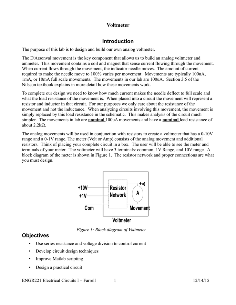
Voltmeter Introduction The purpose of this lab is to design and build our own analog voltmeter. The D'Arsonval movement is the key component that allows us to build an analog voltmeter and ammeter. This movement contains a coil and magnet that sense current flowing through the movement. When current flows through the movement, the indicator needle moves. The amount of current required to make the needle move to 100% varies per movement. Movements are typically 100uA, 1mA, or 10mA full scale movements. The movements in our lab are 100uA. Section 3.5 of the Nilsson textbook explains in more detail how these movements work. To complete our design we need to know how much current makes the needle deflect to full scale and what the load resistance of the movement is. When placed into a circuit the movement will represent a resistor and inductor in that circuit. For our purposes we only care about the resistance of the movement and not the inductance. When analyzing circuits involving this movement, the movement is simply replaced by this load resistance in the schematic. This makes analysis of the circuit much simpler. The movements in lab are nominal 100uA movements and have a nominal load resistance of about 2.2kΩ. The analog movements will be used in conjunction with resistors to create a voltmeter that has a 0-10V range and a 0-1V range. The meter (Volt or Amp) consists of the analog movement and additional resistors. Think of placing your complete circuit in a box. The user will be able to see the meter and terminals of your meter. The voltmeter will have 3 terminals: common, 1V Range, and 10V range. A block diagram of the meter is shown in Figure 1. The resistor network and proper connections are what you must design. Resistor Network Com A Movement Voltmeter +10mA Com + A + A +10V +1V Resistor Network A Movement Ammeter Figure 1: Block diagram of Voltmeter Objectives • Use series resistance and voltage division to control current • Develop circuit design techniques • Improve Matlab scripting • Design a practical circuit ENGR221 Electrical Circuits I – Farrell 1 12/14/15 Voltmeter Procedure Design a dual range voltmeter using an analog D'Arsonval movement. The voltmeter should be able to measure voltages in the range of 0-1V and 0-10V. Your meter should have three terminals: Common, 1V, and 10V. If this was a real meter your breadboard would be off limits to the user. It would be enclosed in a case. So think about how this affects your circuit layout. You must use more than 1 resistor in conjunction with the movement. The resistors used when building your design should nominally be within 1% of your design values, which you should be able to achieve by using combinations of resistors. Make sure you understand parallax reading errors associated with analog movements before you proceed with this lab. Prelab: • Design your circuit and draw your schematic using nominal resistance values. The resistors used in building your design should be within 1% of ideal or design values, which you should be able to achieve by using combinations of resistors. Your completed schematic must show resistor values that are readily available in 5% tolerance, see Appendix H on page 763 of your text. • What is the input resistance of an ideal voltmeter? What is the input resistance of your voltmeter using ideal components? This is the resistance that the user will see if they use an Ohmmeter across the terminals of your voltmeter. You should have two different input resistances, one for each range. • Create a data table to record the actual value of all resistors used. You should also include an actual value of the meter movement's resistance and the voltmeter's input resistance. • Create a data table for characterizing your voltmeter. The table should have columns for ideal voltage, voltage of analog meter, voltage of digital meter, and error calculations. For purposes of error calculations the DMM is considered the ideal value. • Hand draw Schematic 1 as shown below in your notebook. • Write a Matlab script to calculate the ideal values of voltage at nodes A, B, and C shown in Schematic 1 below using nominal values for the resistors. Notice that nodes A, B, and C are each their own voltage divider circuit. Your Matlab script should ask the user for R2, R1, and V1. It should then report the voltage across R2. This is the voltage at node A. You can rerun your script to calculate Node B and Node C voltages. • Create a table to record digital and analog voltage values for measurements taken at nodes A, B, and C in Schematic 1. This table must have room for error calculations between measured values and ideal/nominal; i.e. both the analog and digital voltmeter values will be compared to the ideal/calculated values. Lab: ENGR221 Electrical Circuits I – Farrell 2 12/14/15 Voltmeter 1. Measure and record the input resistance of the analog movement. Be sure to also record what number movement you are using. You will want to use the same movement for all of your experiments. Observe what happens to the movement's needle when you connect it to the DMM: record the reading of the analog meter during the resistance measurement. What does this indicate about how the DMM measures resistance? 2. Measure and record the actual values for all resistors that you will use in your voltmeter design. How do the actual values change the input resistance of your meter? How will this affect the accuracy or range of your meter, be specific? Draw the schematic for your “as built” design showing the nominal resistor values used to construct your meter. Each resistor shown in the schematic must have a reference designator as well as a nominal value. Include a table of actual resistor values. 3. Build and characterize your meter. a. Use your analog meter to set the power supply to 0.2V, 0.4V, 0.6V, 0.8V and 1.0V. At each voltage setting, record the reading with the bench DMM. b. Use your analog meter to set the power supply to 2.0V, 4.0V, 6.0V, 8.0V and 10V. At each voltage setting, record the reading with the bench DMM. 4. Now that the meter is working, let’s test how well it works in a real circuit. Construct the circuit shown in Schematic 1. Use your analog meter and the bench DMM to measure the voltage at nodes A, B, and C as well as the voltage of the power supply. You may have to construct R6 from multiple resistors in your kit. 5 R2 220 R5 1Meg C A V1 R3 47K B R1 100 R4 100K R6 2Meg Schematic 1: Voltmeter test schematic ENGR221 Electrical Circuits I – Farrell 3 12/14/15 Voltmeter Analysis 1. What does the analog needle do when connected to the Ohmmeter? What does this indicate about how the DMM measures resistance? 2. What is the ideal input resistance of your meter? What is the actual input resistance? What is the input resistance of the DMM? (you will have to look this up on the web or in the user manual) A. How does your meter's resistance not being the nominal value affect your voltage readings? 3. Compare all measurements to calculations or ideal. In step 3 you will compare analog voltmeter values to digital voltmeter values. In step 4 you should compare analog voltmeter value to calculated and compare digital voltmeter to calculated. 4. Discuss errors between your analog meter and the digital meter when connected to the power supply. 5. Explain the voltage errors with the test circuit (Schematic 1) A. Remember that the voltmeter can be modeled as a resistor between its terminals B. Why does the digital meter show less error? (look at some of your earlier answers) C. Prove your previous answer for node B of the test circuit (i.e. recalculate the voltage at node B when your voltmeter is connected and when the DMM is connected) 6. You should have seen that your voltmeter measures accurate voltages across some resistors but not across others. What is the largest resistor you feel comfortable placing your voltmeter in parallel with to measure voltage. This is just an estimate, do not calculate a value. However, make sure you can explain your thought process. ENGR221 Electrical Circuits I – Farrell 4 12/14/15


