Model MA-Series Mast Mounted Preamplifiers
advertisement

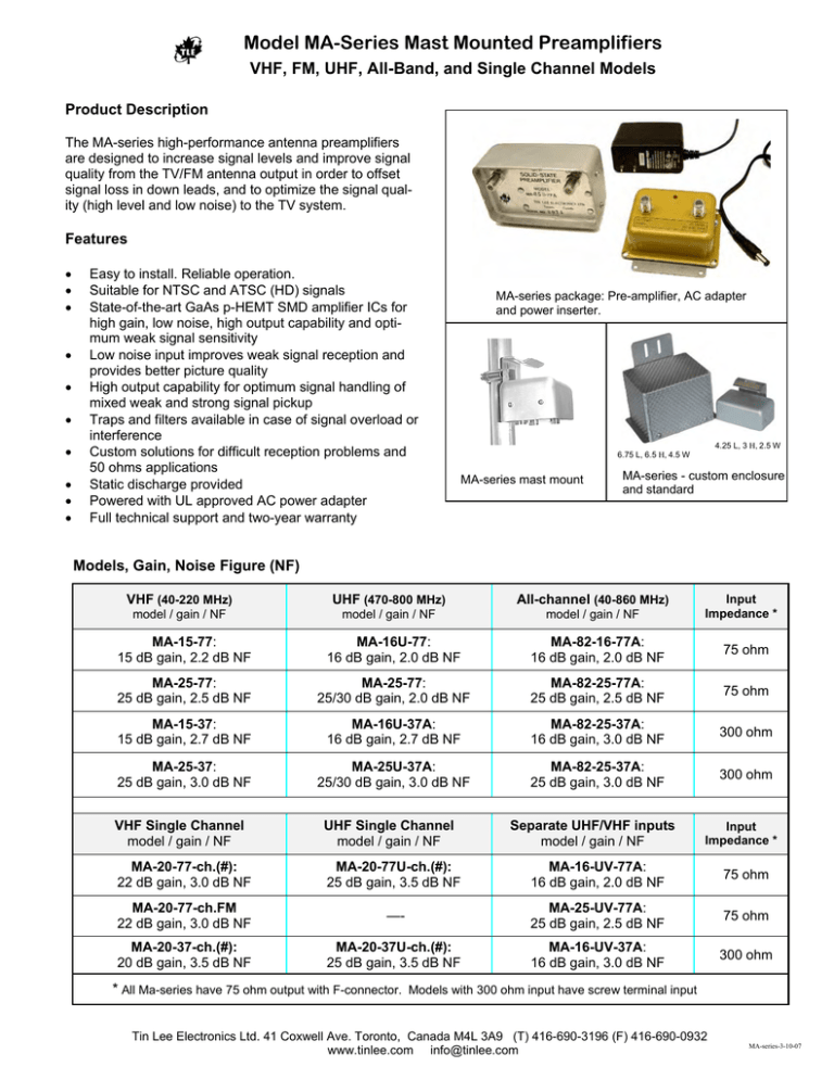
Model MA-Series Mast Mounted Preamplifiers VHF, FM, UHF, All-Band, and Single Channel Models Product Description The MA-series high-performance antenna preamplifiers are designed to increase signal levels and improve signal quality from the TV/FM antenna output in order to offset signal loss in down leads, and to optimize the signal quality (high level and low noise) to the TV system. Features • • • • • • • • • • Easy to install. Reliable operation. Suitable for NTSC and ATSC (HD) signals State-of-the-art GaAs p-HEMT SMD amplifier ICs for high gain, low noise, high output capability and optimum weak signal sensitivity Low noise input improves weak signal reception and provides better picture quality High output capability for optimum signal handling of mixed weak and strong signal pickup Traps and filters available in case of signal overload or interference Custom solutions for difficult reception problems and 50 ohms applications Static discharge provided Powered with UL approved AC power adapter Full technical support and two-year warranty MA-series package: Pre-amplifier, AC adapter and power inserter. 4.25 L, 3 H, 2.5 W 6.75 L, 6.5 H, 4.5 W MA-series mast mount MA-series - custom enclosure and standard Models, Gain, Noise Figure (NF) VHF (40-220 MHz) UHF (470-800 MHz) All-channel (40-860 MHz) model / gain / NF model / gain / NF model / gain / NF Input Impedance * MA-15-77: 15 dB gain, 2.2 dB NF MA-16U-77: 16 dB gain, 2.0 dB NF MA-82-16-77A: 16 dB gain, 2.0 dB NF 75 ohm MA-25-77: 25 dB gain, 2.5 dB NF MA-25-77: 25/30 dB gain, 2.0 dB NF MA-82-25-77A: 25 dB gain, 2.5 dB NF 75 ohm MA-15-37: 15 dB gain, 2.7 dB NF MA-16U-37A: 16 dB gain, 2.7 dB NF MA-82-25-37A: 16 dB gain, 3.0 dB NF 300 ohm MA-25-37: 25 dB gain, 3.0 dB NF MA-25U-37A: 25/30 dB gain, 3.0 dB NF MA-82-25-37A: 25 dB gain, 3.0 dB NF 300 ohm VHF Single Channel model / gain / NF UHF Single Channel model / gain / NF Separate UHF/VHF inputs model / gain / NF MA-20-77-ch.(#): 22 dB gain, 3.0 dB NF MA-20-77U-ch.(#): 25 dB gain, 3.5 dB NF MA-16-UV-77A: 16 dB gain, 2.0 dB NF 75 ohm MA-20-77-ch.FM 22 dB gain, 3.0 dB NF —- MA-25-UV-77A: 25 dB gain, 2.5 dB NF 75 ohm MA-20-37-ch.(#): 20 dB gain, 3.5 dB NF MA-20-37U-ch.(#): 25 dB gain, 3.5 dB NF MA-16-UV-37A: 16 dB gain, 3.0 dB NF 300 ohm Input Impedance * * All Ma-series have 75 ohm output with F-connector. Models with 300 ohm input have screw terminal input Tin Lee Electronics Ltd. 41 Coxwell Ave. Toronto, Canada M4L 3A9 (T) 416-690-3196 (F) 416-690-0932 www.tinlee.com info@tinlee.com MA-series-3-10-07 Model MA-Series Mast Mounted Preamplifiers VHF, FM, UHF, All-Band, and Single Channel Models Specifications Category Model Gain (min) VHF, FM UHF All-Band Noise Figure Frequency Coverage Maximum Input /Output Capability Application MA-15-37 MA-15-77 15 dB 15 dB 3.5 dB 3. dB 40-230 MHz 40-230 MHz 28 dBmV / 8 chs; 43 dBmV /8 chs Fringe area MA-25-37 MA-25-77 25 dB 25 dB 3.5 dB 3 dB 40-230 MHz 40-230 MHz 22 dBmV / 8 chs; 47 dBmV /8 chs Deep fringe MA-20-37-ch.# * MA-20-77-ch.# * MA-20-77-ch.FM * 22 dB 22 dB 22 dB 4.0 dB 3.5 dB 3.5 dB 6 MHz VHF 6 MHz VHF FM (88-108 MHz) 30 dBmV / 1 ch 52 dBmV /1 ch “ Fringe-Deep fringe MA-16U-37A MA-16U-77A 16 dB 16 dB 3.0 dB 2.5 dB 470-870 MHz 470-870 MHz 30 dBmV / 8 chs; 46 dBmV /8 chs Fringe area MA-25U-37A MA-25U-77A 25 dB 25 dB 3.0 dB 2.5 dB 470-870 MHz 470-870 MHz 21 dBmV / 8 chs; 46 dBmV /8 chs Deep fringe MA-20-37-ch.# * MA-20-77-ch.# * 25 dB 25 dB 4.0 dB 3.5 dB 6 MHz UHF 6 MHz UHF 27 dBmV / 1 ch 52 dBmV /1 ch Fringe-Deep fringe MA-82-16-37A MA-82-16-77A 16 dB 16 dB 3.0 dB 2.5 dB 40-870 MHz 40-870 MHz 30 dBmV / 8 chs; 46 dBmV /8 chs Fringe area MA-82-25-37A MA-82-25-77A 25 dB 25 dB 3.0 dB 2.5 dB 40-870 MHz 40-870 MHz 21 dBmV / 8 chs; 46dBmV /8 chs Deep fringe MA-16UV-37A MA-16UV-77A 16 dB 16 dB 3.0 dB 2.5 dB 30 dBmV / 8 chs; 46 dBmV /8 chs Fringe-Deep fringe MA-25-UV77A 25 dB 2.5 dB 40-230, 470-870 MHz. Separate VHF, UHF inputs “ Common Specifications Output Impedance/Connector 75 ohms type F– female Recommended Minimum Input -15 dBmV VHF Preamplifier Power and Power Requirements -18 V DC, +110 VAC Adapter UHF/All-band Preamplifier Power and Power Requirements +18 V DC, +110 VAC Adapter Shipping weight 2 lbs (pre-amplifier, power supply) Dimensions (in): Preamplifier 4.25 L, 3 H, 2.5 W Dimensions (in): Power Inserter, AC adapter 3.125 L, 3.125W, 2 H Warranty 2 years, parts and labour Connectors F-61 (75 ohm) and Screw terminal (300 ohms) Notes: • Single channel models have Input bandpass with 2 dB insertion loss • Option: Custom models requiring 50 ohms impedance available with BNC, N, or sma connectors • When traps and filters are required ahead of preamp, use 75 ohm shielded cable to 75 ohm input Tin Lee Electronics Ltd. 41 Coxwell Ave. Toronto, Canada M4L 3A9 (T) 416-690-3196 (F) 416-690-0932 www.tinlee.com info@tinlee.com Tin Lee Electronics MA-Series Preamplifier Hookup HOOKUP MA-PREAMP All Band VHF/UHF PreampHookup-1-27-07 VHF/UHF Antenna Equipment: MA82-25-77A Mounting Clamp, Power inserter (DR-82-18V), AC Adapter Hookup Procedure Optional RF Filter (e.g., FM Bandstop) Refer to diagram before hooking up equipment 1. Connect Antenna to MA-PREAMP INPUT 2. Connect MA-UHF PREAMP OUTPUT to DR-82-18VDC 3. Connect DR-82+18V to TV System 4. Check ground system for antenna/mast * 5. Connect AC Power Adapter TV OUTPUT DC IN ANTENNA INPUT 1 2 Disconnect Procedure MA-82-25-77A Disconnect Power before disconnecting Antenna from INPUT. 75 ohm coaxial Cable connection ( DC voltage is supplied to the Preamp ) +18Vdc TV/RF 75 ohm downlead *Reminder: Antenna Ground System MA-Preamplifier mounted outdoors To protect pre-amplifier and antenna user, Antenna mast should have a good ground system. Properly ground antenna mast to prevent static charge accumulation on antenna and protect against lightning damage. Refer to antenna installation manual for details. MA-Series Power Supply Pre-amplifier Ground clamp To Amp “OUT” TV/RF OUT To TV System DR-82+18VDC Mast Ground Wire Antenna Downlead 3 +18Vdc* To TV System Lightning arrestor Ground wire AC-adaptor +18V DC +18Vdc 110V AC Wall Outlet Ground clamps This section for indoor installation Tin Lee Electronics Ltd. 41 Coxwell Ave. Toronto, Canada M4L 3A9 (T) 416-690-3196 (F) 416-690-0932 www.tinlee.com info@tinlee.com Tin Lee Electronics MA-Series Preamplifier Hookup Example Application: Hookup Two Separate MA-preamplifiers (UHF and VHF) Two pre-amplifiers are supplied from one power supply and outputs are combined for single drop line. Separate pre-amplifiers for different gain requirements- UHF band need greater gain than VHF band. UHF/VHF combiner is power passing through all ports Equipment: MA-Preamplifiers ( MA-25U-77A, MA-15-77), Mounting Clamp, Power inserter (DR-82-18V), AC Adapter, and UV7X DC (power passing) VHF UHF Hookup Procedure Refer to diagram before hooking up equipment 1. Connect Antenna to MA-PREAMP INPUTS 2. Connect MA-PREAMP OUTPUTS to DR-82-18V 3. Connect DR-82-18V to TV System 4. Connect AC Power adapter. Reminder - provide ground system for antenna/mast * 1 TV OUTPUT DC IN ANTENNA INPUT ANTENNA INPUT 1 TV OUTPUT DC IN 2 2 MA-25U-77A MA-15-77 UHF VHF UV7X-DC DC voltage is supplied to both the Preamps Disconnect Procedure +18Vdc Disconnect Power before disconnecting Antenna from INPUT. TV/RF 75 ohm downlead MA-Preamplifiers mounted outdoors *Reminder: Antenna Ground System To protect pre-amplifier and antenna user, Antenna mast should have a good ground system. Properly ground antenna mast to prevent static charge accumulation on antenna and protect against lightning damage. Refer to antenna installation manual for details. MA-Series Power Supply To Amp “OUT” TV/RF OUT To TV System DR-82Pre-amplifier 75 ohm coaxial Cable connection ( DC voltage is supplied to the Preamp ) Ground clamp Mast Ground Wire 110V AC Wall Outlet 3 +18Vdc Antenna Downlead To TV System Lightning arrestor Ground wire +18Vdc AC-adaptor +18V DC This section for indoor installation Ground clamps Tin Lee Electronics Ltd. 41 Coxwell Ave. Toronto, Canada M4L 3A9 (T) 416-690-3196 (F) 416-690-0932 www.tinlee.com info@tinlee.com


