XT® BUSHING INSTALLATION AND OPERATION
INSTRUCTIONS FOR CONVEYOR PULLEYS
EQUIPPED WITH XT HUBS
DO NOT USE XT® BUSHINGS IN ANY PRODUCT
OTHER THAN XT HUBS
BEFORE INSTALLATION:
1. Make sure that the shaft, barrel & bore of the bushing, XT bushed conveyor
pulley hub bores, keys and keyways are clean and free of burrs, paint, etc.
2. For proper operation, make sure that the shaft size is within the size limits shown
in Table 1. Some applications may benefit from tighter shaft tolerances.
!
WARNING
!
CAUTION
Mounting a XT Bushing on a shaft smaller than the size
limits shown in Table 1 may result in a faulty assembly.
The assembly may come off the shaft or undesirable
assembly run out may result.
MOUNTING:
3. Using a hoist or other appropriate means, place the shaft through the pulley
being careful not to damage the bore of the hub(s) and locate in the desired
position. When mounting on an inclined surface, if required, make sure the
conveyor pulley and shaft do not drop during installation.
To avoid damage, supporting structure
including shafts and bearings must be
designed to handle transmitted loads
and belt tension(s).
4. It may be necessary to slightly wedge open the saw slot on some Bushings in
order to start the bore and position the bushing onto the shaft. A narrow edged
regular screw driver may be used.
Excessive wedging forces in Bushing saw slot may
damage or break Bushing. AVOID.
5. Align the shaft keyseat with the Bushing bore keyway and install the key. Make
sure the key runs the entire length of the bushing bore.
For XT Conveyor Pulleys requiring two bushings, shaft keyways must be in
linewith each other for proper bushing installation. Some Bushings with
shallow keyways are supplied with shaft keys. For proper operation use the
key supplied with the bushing.
!
WARNING
Lubricant on bushing barrel, hub or
screws could lead to breakage.
To assure proper transmission of torque, all bushings
used in drive pulleys must be keyed to the shaft.
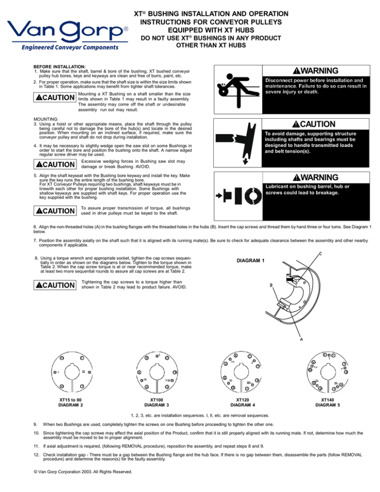
6. Align the non-threaded holes (A) in the bushing flanges with the threaded holes in the hubs (B). Insert the cap screws and thread them by hand three or four turns. See Diagram 1
below.
7. Position the assembly axially on the shaft such that it is aligned with its running mate(s). Be sure to check for adequate clearance between the assembly and other nearby
components if applicable.
8. Using a torque wrench and appropriate socket, tighten the cap screws sequentially in order as shown on the diagrams below. Tighten to the torque shown in
Table 2. When the cap screw torque is at or near recommended torque, make
at least two more sequential rounds to assure all cap screws are at Table 2.
DIAGRAM 1
Tightening the cap screws to a torque higher than
shown in Table 2 may lead to product failure. AVOID.
XT15 to 80
DIAGRAM 2
XT100
DIAGRAM 3
XT120
DIAGRAM 4
XT140
DIAGRAM 5
1, 2, 3, etc. are installation sequences. I, II, etc. are removal sequences.
9.
When two Bushings are used, completely tighten the screws on one Bushing before proceeding to tighten the other one.
10. Since tightening the cap screws may affect the axial position of the Product, confirm that it is still properly aligned with its running mate. If not, determine how much the
assembly must be moved to be in proper alignment.
11. If axial adjustment is required, (following REMOVAL procedure), reposition the assembly, and repeat steps 8 and 9.
12. Check installation gap - There must be a gap between the Bushing flange and the hub face. If there is no gap between them, disassemble the parts (follow REMOVAL
procedure) and determine the reason(s) for the faulty assembly.
© Van Gorp Corporation 2003. All Rights Reserved.
XT® BUSHING INSTALLATION AND OPERATION
INSTRUCTIONS FOR CONVEYOR PULLEYS
EQUIPPED WITH XT HUBS (Cont’d.)
REMOVAL:
1. Remove all cap screws sequentially as shown on Diagrams 2, 3, 4 and 5 using the
Roman numeral sequence.
2. Heavier Product may require a hoist or other means of supporting the Product during the
remainder of removal procedure. When removing from an inclined surface, make sure
the Bushing and Product do not drop during removal.
3. Insert cap screws in all threaded Bushing flange holes (C). Tighten the cap screws against
hub face of the Product until the screw force releases the Product from the Bushing. If
the Bushing does not release immediately, tap on the hub with a hammer.
4. When two Bushings are used, completely loosen the screws on one Bushing before proceeding to loosen the other one.
5. Remove the Bushing(s) and Product from the shaft using appropriate means.
TABLE 1
RECOMMENDED WRENCH TORQUE
Shaft Size
Range (IN)
Shaft Size
Range (MM)
Lower Shaft
Size Limit
(IN)
Above
Through
1 1/2
-0.003
1 1/2
2 1/2
-0.004
2 1/2
4
-0.005
4
6
-0.006
6
8
-0.007
8
9
-0.008
9
-0.009
Note: Upper limit is +0 whether units are INCHES or MILLIMETERS.
Above
38.1
63.5
101.6
152.4
203.2
228.6
Through
38.1
63.5
101.6
152.4
203.2
228.6
-
Lower Shaft
Size Limit
(MM)
-0.076
-0.102
-0.127
-0.152
-0.178
-0.203
-0.229
TABLE 1
RECOMMENDED WRENCH TORQUE
SAE Grade 5
Cap Screw
NO.
SIZE
15
4
1/4 - 20NC
20
4
5/16 - 18NC
25
4
3/8 - 16NC
30
4
7/16 - 14NC
35
4
1/2 - 13NC
40
4
9/16 - 12NC
45
4
5/8 - 11NC
50
4
3/4 - 10NC
60
4
7/8 - 9NC
70
4
1 - 8NC
80
4
1 1/8 - 7NC
100
6
1 1/8 - 7NC
120
8
1 1/8 - 7NC
140
10
1 1/8 - 7NC
(N - M) = Newton Meters
XT
SIZE
CAP SCREW TORQUE
(IN-LBS)
95
192
348
552
840
1200
1680
3000
4800
7200
9000
9000
9000
9000
(FT-LBS)
8
16
29
46
70
100
140
250
400
600
750
750
750
750
(N - M)
10.7
21.7
39.3
62.4
94.9
135.6
189.8
339.0
542.3
813.5
1016.9
1016.9
1016.9
1016.9
OPERATING INSTRUCTIONS:
1.
All pulleys should be checked for tightness on their shafts.
NOTE: For the first month of operation, inspect the bushings for proper seating and cap screws for correct cap screw torque at least once a week and thereafter during
periodic shutdowns.
2.
The pulley lagging should be checked for wear, cracks, and tightness. Changes in coefficient of friction between the drive pulleys and belt could result in belt slippage.
3.
The ends of pulleys should be inspected for cracks or other signs of stress or fatigue. The pulley should not be operated if a crack develops.
4.
Take-up pulleys and belt tensioning devices should function normally. Excessive belt tension could fail pulleys, bearings and shafts.
5.
Pulleys should be checked for vertical and lateral alignment. Misalignment can result in belt tracking problems and pulley wear.
6.
Bearings should be visually checked for excessive shaft movement in the bearing during operation.
7.
All bearings should be checked for alignment, lubrication, and tightness of locking devices.
8.
Conveyor pulleys should not be cleaned during operation. It is extremely dangerous to be near the nip point when the pulley is in operation.
9.
The conveyor should not be operated without the necessary protective guards.
Printed in U.S.A.
© Van Gorp Corporation 2003. All Rights Reserved.
VAN GORP CORPORATION
1410 WASHINGTON ST
PELLA, IA 50219


