GE
Security
Overview
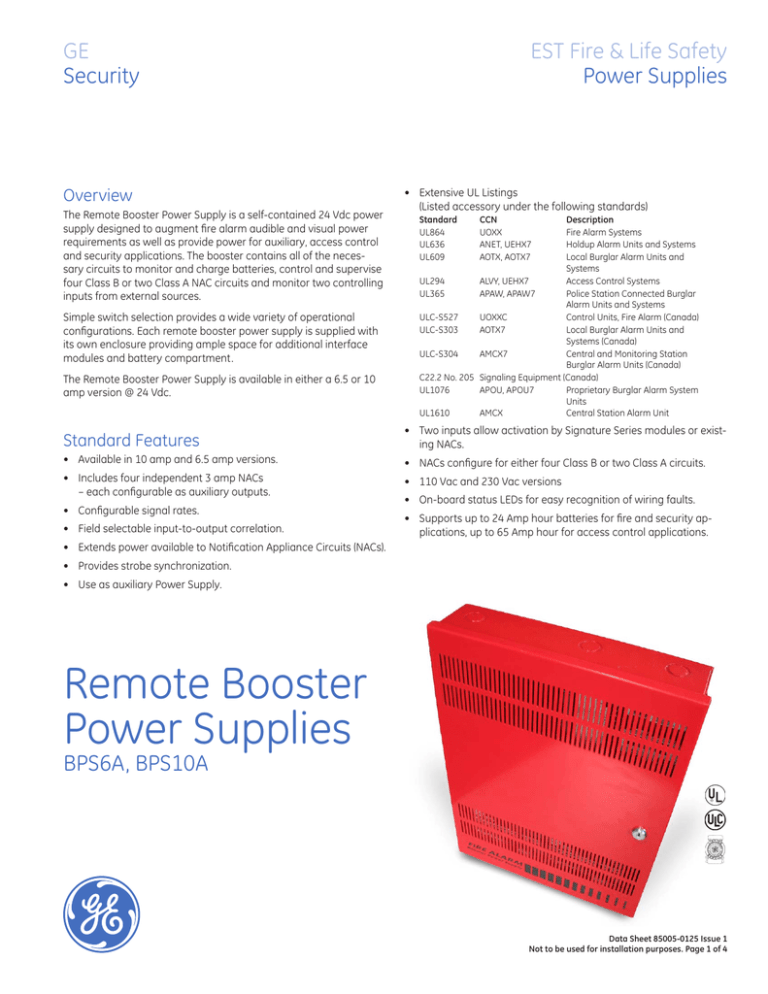
The Remote Booster Power Supply is a self-contained 24 Vdc power
supply designed to augment fire alarm audible and visual power
requirements as well as provide power for auxiliary, access control
and security applications. The booster contains all of the necessary circuits to monitor and charge batteries, control and supervise
four Class B or two Class A NAC circuits and monitor two controlling
inputs from external sources.
Simple switch selection provides a wide variety of operational
configurations. Each remote booster power supply is supplied with
its own enclosure providing ample space for additional interface
modules and battery compartment.
The Remote Booster Power Supply is available in either a 6.5 or 10
amp version @ 24 Vdc.
EST Fire & Life Safety
Power Supplies
• Extensive UL Listings
(Listed accessory under the following standards)
Standard
CCN
Description
UL864
UOXX
Fire Alarm Systems
UL636
ANET, UEHX7
Holdup Alarm Units and Systems
UL609
AOTX, AOTX7
Local Burglar Alarm Units and Systems
UL294
ALVY, UEHX7
Access Control Systems
UL365
APAW, APAW7
Police Station Connected Burglar Alarm Units and Systems
ULC-S527
UOXXC
Control Units, Fire Alarm (Canada)
ULC-S303
AOTX7
Local Burglar Alarm Units and Systems (Canada)
ULC-S304
AMCX7
Central and Monitoring Station Burglar Alarm Units (Canada)
C22.2 No. 205 Signaling Equipment (Canada)
UL1076
APOU, APOU7
Proprietary Burglar Alarm System Units
UL1610
AMCX
Central Station Alarm Unit
Standard Features
• Two inputs allow activation by Signature Series modules or existing NACs.
• Available in 10 amp and 6.5 amp versions.
• NACs configure for either four Class B or two Class A circuits.
• Includes four independent 3 amp NACs
– each configurable as auxiliary outputs.
• 110 Vac and 230 Vac versions
• Configurable signal rates.
• Field selectable input-to-output correlation.
• On-board status LEDs for easy recognition of wiring faults.
• Supports up to 24 Amp hour batteries for fire and security applications, up to 65 Amp hour for access control applications.
• Extends power available to Notification Appliance Circuits (NACs).
• Provides strobe synchronization.
• Use as auxiliary Power Supply.
Remote Booster
Power Supplies
BPS6A, BPS10A
Data Sheet 85005-0125 Issue 1
Not to be used for installation purposes. Page of 4
Application
The Remote Booster Power Supply provides additional power for
audible and visual devices helping remove system capacity or site
application constraints. The booster may also be used to power
auxiliary, access control and security devices, in addition to fire
devices.
Fault conditions detected by the BPS will open the main panel’s
NAC. This initiates a trouble condition and eliminates the need to
wire a separate trouble contact back to the control panel. During
alarm condition, detected faults are overridden and the main panel’s default configuration is continuous 24 Vdc on all NACs typically
used to drive visual devices. On board trouble contact is supplied for
applications requiring trouble contact monitoring.
The booster power supply provides the capability to maximize
available power by being able to supply power for multiple services
including Access Control, Security and Fire. For security applications, space is provided to mount a tamper switch in the cabinet.
When used for Fire Alarm notification with Genesis Notification appliances, the booster provides the ability to synchronize strobes as
well as horn signals. The booster flexibility allows synchronization
with upstream devices, or, the booster may be used to synchronize
downstream devices, as well as other boosters and their connected
devices. Up to 10 boosters deep may be configured while maintaining strobe synchronization.
BPS notification appliance circuits easily configure for either of two
signaling rates: 3-3-3 temporal or continuous. California rate is also
available on certain models. This makes the BPS ideal for applications requiring signaling rates not available from the main panel.
It also allows independent setup of a notification appliance circuit
without interfering with the main panel and its initiating circuits.
In addition to the generated signal rates, the BPS can also be
configured to follow the signal rate of the main panel’s notification
appliance circuit. This allows seamless expansion of existing NACs.
resident NAC; one for battery supervision; one for ground fault; and,
one for ac power. The trouble contact has a sixteen second delay
when an ac power failure or brownout condition is detected. This
reduces the reporting of troubles during short duration ac brownouts.
NAC configuration options include: ac power fail delay (16 seconds
or 6 hours); sensing input to NAC output correlations; and, auxiliary
outputs. All NACs are configurable as auxiliary outputs. Auxiliary
outputs can be always on, or off after 30 seconds without ac power.
As auxiliary output, the booster may power access control and
security devices. Should an overcurrent occur, the booster automatically opens the circuit. The booster automatically restores the
circuit when the overcurrent is removed. Jumpers configure the
BPS for Class A or Class B wiring.
Engineering Specification
Supply where needed GE Security BPS series Booster Power Supplies as an extension of Notification Appliance Circuits. The extension shall be in the form of a stand alone booster power supply. The
supply must incorporate its own standby batteries. Batteries must
be sized for <24>, <60> hours of standby followed by <5>, <30>
minutes of alarm. It must be possible to support up to 24 Amp hour
batteries.
The booster supply must incorporate four independent supervised
Notification Appliance Circuits. It shall be possible to configure the
NACs to follow the main panel’s NAC or activate from intelligent
Signature Series modules. The booster NACs must be configurable
to operate independently at any one of the following rates: continuous, California Rate, or 3-3-3 temporal. Fault conditions on the
booster shall not impede alarm activation of host NAC circuits.
The BPS includes seven on-board LED indicators: one for each
The booster must be able to provide concurrent power for Notification devices, Security devices, Access Control equipment and Auxiliary devices such as door holders. The BPS must provide the ability
to synchronize Genesis series strobes and horns.
Dimensions
Wire routing
D5
Top View
D2
D3
D4
Side View
Front View
D1
D6
Side View
All knockouts
for 3/4 in conduit
(1.9 cm)
D1
D2
D3
D4
D5
D6
Notes
1. Maintain 1/4-inch (6
mm) spacing between
power-limited and nonpower-limited wiring or
use type FPL, FPLR, or
FPLP cable per NEC.
[2] Power-limited and
supervised when not
configured as auxiliary
power. Non-supervised
when configured as
auxiliary power.
[3] Source must be powerlimited. Source determines supervision.
4. When using larger
batteries, make sure
to position the battery
terminals towards the
door.
17.0 in
3.5 in
13.0 in
6.5 in
3.375 in 12.0 in
(43.2 cm) (8.9 cm) (33.0 cm) (16.5 cm) (8.6 cm) (30.4 cm)
Data Sheet 85005-0125 Issue 1
Not to be used for installation purposes. Page of 4
Typical Wiring
Booster Power
Supply
Multiple CC1(S) modules using the
BPS’s sense inputs
+
+
200 mA AUX
Continuous
IN
Sense 1 COM
OUT
IN
Sense 2 COM
OUT
NO
Trouble COM
NC
Sense 1 Input
To next signaling
device, booster, or
EOL resistor
NAC output #1
NAC output #2
NAC output #3
NAC output #4
Booster Power
Supply
UL listed
EOL 15 K
+
Sense 1 Input
Booster Power
Supply
Notification appliance circuit (NAC)
EOL 47 K
+
To next signaling
device, booster, or
EOL resistor
NAC output #1
NAC output #2
NAC output #3
NAC output #4
[APP-03.CDR]
UL listed
EOL 15 K
+
Booster Power
Supply
Notification appliance circuit (NAC)
+
NAC output #4
TB1
TB5
NAC1/
AUX1
NAC2/
AUX2
NAC3/
AUX3
NAC4/
AUX4
NAC output #1
NAC output #2
NAC output #3
Sense 1 Input
Fire Alarm
Control Panel
NAC output #1
NAC output #2
NAC output #3
NAC output #4
Sense 2 Input
Fire Alarm
Control Panel
To next signaling
device, booster, or
EOL resistor
NAC Circuit
Sense 1 Input
Existing NAC end-of-line resistors are not required to be
installed at the booster’s terminals. This allows multiple
boosters to be driven from a single NAC circuit without the
need for special configurations.
Multiple boosters cascaded
from a single notification appliance circuit
To next signaling
device, booster, or
EOL resistor
NAC Circuit
NAC Circuit
Single booster anywhere on
a notification appliance circuit
EOL 47 K
+
+
10 9
10 9
CC1(S) module
TB2
8765
+ +
CC1(S) module
4 321
[1]
4 321
8765
[1]
+ +
[3]
Security and access
BPS
24 V
12 V
Security
device
24DC12
EOL
monitoring
device
Security
device
+
+
+
+
NAC1/
AUX1
NAC2/
AUX2
NAC3/
AUX3
NAC4/
AUX4
TB1
Control panel
+
Card reader
controller
+
Card reader
controller
+
BPS [1]
+
Card reader
controller
+
[1] Disable the BPS’s ground fault jumper (JP3)
To next
device
or end
Data Sheet 85005-0125 Issue 1
Not to be used for installation purposes. Page of 4
GE
Security
U.S.
T 888-378-2329
F 866-503-3996
Canada
T 519 376 2430
F 519 376 7258
Asia
T 852 2907 8108
F 852 2142 5063
Australia
T 61 3 9259 4700
F 61 3 9259 4799
Europe
T 32 2 725 11 20
F 32 2 721 86 13
Latin America
T 305 593 4301
F 305 593 4300
www.gesecurity.com
© 2006 General Electric Company
All Rights Reserved
Specifications
Model
6.5 amp Booster
120VAC or 220-240VAC 50/60Hz
250 watts
Notification Appliance
Circuit Ratings
3.0A max. per circuit @ 24Vdc
3.0A max. per circuit @ 24Vdc
nominal 10A max total all NACs
nominal 6.5A max total all NACs
2 Amps @ 30Vdc
Trouble Relay
Auxiliary Outputs
Input Current
(from an existing NAC)
Four configurable outputs replace NACs 1, 2, 3 or 4. as auxiliary outputs
and 200 mA dedicated auxiliary. (See note 2.)
3mA @ 12Vdc, 6mA @ 24Vdc
70mA
Booster Internal
Supervisory Current
Accomodates three two-gang modules.
Signature Mounting Space
Maximum Battery Size
10 Amp Hours (2 of 12V10A) in cabinet up to 24 Amp hours with external battery cabinet for fire and security applications; up to 65 Amp
hours for access control applications in external battery box.
Terminal Wire Gauge
Relative Humidity
18-12 AWG
0 to 93% non condensing @ 32°C
Temperature Rating
NAC Wiring Styles
32° to 120°F (0° to 49°C)
Class A or Class B
Output Signal Rates
Signature Series is a Trademark
of GE Security.
10 amp Booster
120VAC or 220-240VAC 50/60Hz
375 watts
AC Line Voltage
Ground Fault Detection
Agency Listings
Continuous, California rate, 3-3-3 temporal,
or follow installed panel’s NAC. (See note 1.)
Enable or Disable via jumper
UL, ULC, CSFM
Notes
1. Model BPS*CAA provides selection for California rate, in place of temporal.
2. Maximum of 8 Amps can be used for auxiliary output.
Ordering Information
Catalog
Number
BPS6A
BPS6A/230
BPS6CAA
BPS10A
BPS10A/230
BPS10CAA
Description
6.5 Amp Booster Power Supply
6.5 Amp Booster Power Supply (220V)
6.5 Amp Booster Power Supply with California rate
10 Amp Booster Power Supply
10 Amp Booster Power Supply (220V)
10 Amp Booster Power Supply with California rate
Related Equipment
12V6A5
7.2 Amp Hour Battery, two required
12V10A
10 Amp Hour Battery, two required
3-TAMP
Tamper switch
BC-1
Battery Cabinet (up to 2 - 40 Amp Hour Batteries)
BC-2
Battery Cabinet (up to 2 - 17 Amp Hour Batteries)
12V17A
18 Amp Hour Battery, two required (see note 1)
12V24A
24 Amp Hour Battery, two required (see note 1)
12V40A
40 Amp Hour Battery, two required (see notes 1, 2)
12V50A
50 Amp Hour Battery, two required (see notes 1, 2)
12V65A
65 Amp Hour Battery, two required (see notes 1, 2)
Shipping Wt.
lb (kg)
13 ( 5.9)
13 ( 5.9)
13 ( 5.9)
13 ( 5.9)
13 ( 5.9)
13 ( 5.9)
3.4 (1.6)
9.5 (4.3)
58 (26.4)
19 (8.6)
13 ( 5.9)
20 (9.07)
32 (14.5)
40 (18.14)
49 (22.2)
Notes
1. Requires installation of separate battery cabinet.
2. BPS supports batteries greater than 24 Amp hours for access control applications only.
Data Sheet 85005-0125 Issue 1
Not to be used for installation purposes. Page of 4


