SenSei - 5 Wits Productions, Inc.
advertisement

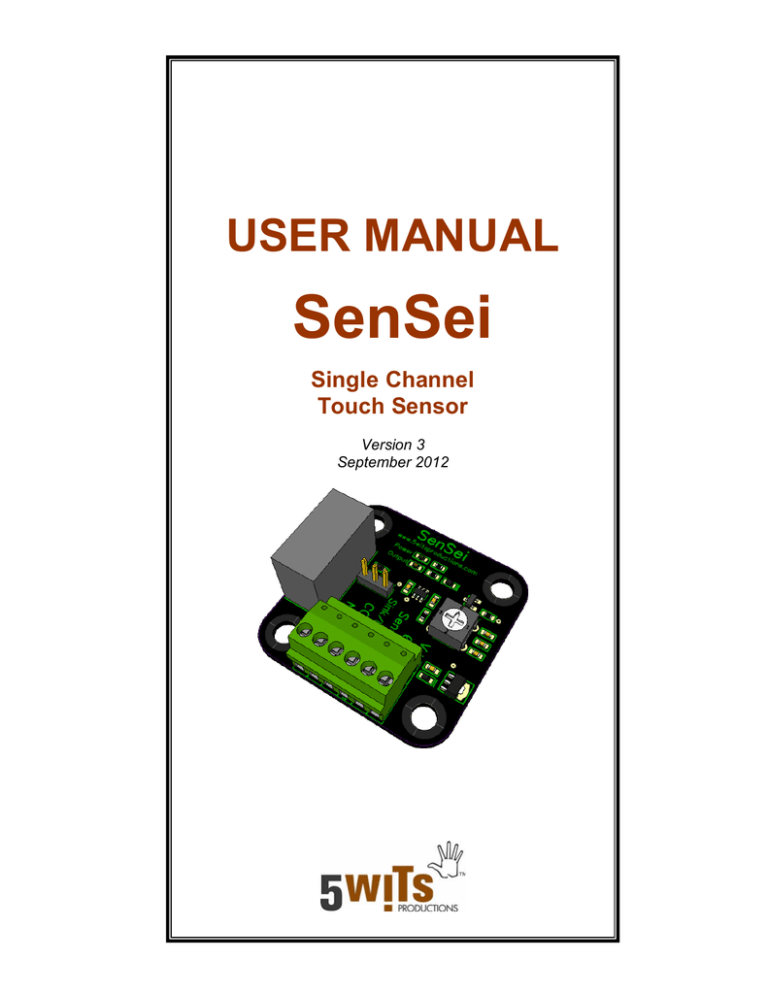
USER MANUAL SenSei Single Channel Touch Sensor Version 3 September 2012 SenSei USER MANUAL VERSION 3 SenSei USER MANUAL Single Channel Touch Sensor FEATURES SPECIFICATIONS Allows any small, conductive metal object to be used as a vandal-proof, weatherproof touch switch Single output touch switch, with power and output LED indicators On board voltage regulator accepts a wide range of input voltages (8-24 VDC) Dry contact relay output capable of switching up to 5A @ 250VAC / 30VDC Open collector (sinking transistor) output capable of sinking up to 350mA @ 24VDC. Touch sensor sensitivity can be configured with an onboard 4-position switch. With proper design of your sensing "electrode," this unit can detect proximity, or "near touch," through air or a variety of dielectrics such as plastic, wood, or glass. Removable / repositionable terminal block makes wiring much easier. Input Power Requirement 8-24 VDC @ 100mA minimum TYPICAL APPLICATIONS Finger activated touch—the ultimate durability replacement for pushbuttons Interactive museum exhibits Hand or foot proximity detection “Seat occupied” detector Animal detection Monitor for liquid levels Monitor for materials handling Specialized input interface for a PLC, microcontroller, show control system, or computer www.5WitsProductions.com LED Indicators Red output indicator Green power indicator Connections All connections are made using removable terminal blocks Accepts wire 16-26 gauge Input Signal A one-wire connection turns nearly any small, metal objects into a touch-switch. It is possible to create a system that detects proximity inches away through the air or any dielectric, such as glass, plastic, ceramic, or wood, in addition to sensing touch directly. Outputs There are two jumper-selectable output modes available: o SPDT relay rated for switching 5A @ 250VAC / 30VDC o Open collector (sinking transistor) output rated for 350mA @ 24VDC High quality relays have an average life of 30,000 cycles at their full rated load, up to 2,000,000 cycles at no load. Screw terminals are provided for normally open and normally closed relay contacts, as well as the open collector. Page 2 of 6 SenSei USER MANUAL VERSION 3 PHYSICAL DIMENSIONS Mounting The four mounting holes are 0.20 inches in diameter and are located on 1.30 inch centers. This size hole is suitable for mounting with a #8 or #10 machine screw, or a simple wood/drywall screw. Care should be taken not to attach the PCB down on a conductive surface, as there are exposed traces on the bottom. TYPICAL WIRING Relay Output www.5WitsProductions.com Open Collector Output Page 3 of 6 SenSei USER MANUAL VERSION 3 USING THE TOUCH SENSOR Touch sensing technology has been around for many years, but recent advances in mixed signal programmable devices are increasingly making capacitance-based touch sensors a practical and value-added alternative to mechanical switches in a wide range of products and applications. The device is designed specifically for human interfaces, although it may also be used in some material sensing applications. Slow, regular recalibration eliminates the all too common “stuck sensor” condition of lower quality touch sensors, and eliminates problems caused by variances and signal drift over time from component aging and temperature changes. This model of the SenSei will reset a “stuck” input, if that input remains high for roughly 60 seconds. This means, if you finger remains on the electrode and the SenSei is “sensing” for roughly 60 seconds, it will automatically switch the output off and recalibrate. Sensitivity Configuration Switch An onboard rotary switch allows for sensitivity adjustment. Use a small screwdriver to gently turn the arrow on the switch from 1 (least sensitive) to 4 (most sensitive). Power cycle the device after adjusting sensitivity for the best results. Low Medium Low Medium High High 0 1 2 3 www.5WitsProductions.com Output Configuration Jumper An onboard jumper allows the board to be operated in relay or open collector (sinking transistor) output mode. The sensor must be run in one mode or the other. When run in “Sink” position, the relay is never energized, causing the touchsensor to operate silently. Sink Position Relay Position Electrode Selection The design, wiring, and layout of your sensing electrodes is of great importance in creating a robust, reliable touch sensing system. The “load capacitance” of your electrode is a factor in the sensitivity of the system. The touch sensor detects the change in capacitance caused by the proximity or touch of a person or object—if the change is too small, relative to the initial load capacitance on the system, the device will detect unreliably or not at all. Thus, the metal object used as a sensing electrode cannot be too large, or the device will not see enough of a change when touched by a person. Trial and error is helpful in electrode selection. In general, any “hand held” size metal object will work well. If you are attempting to detect with a large electrode plate, one option is to use a mesh screen instead of a solid metal object, to decrease the initial load capacitance of the system, but still provide a wide detection area. Page 4 of 6 SenSei USER MANUAL VERSION 3 When attempting to detect through a dielectric panel, such as plastic, wood, or glass, sensitivity can be increased by using a larger electrode area, reducing the panel thickness, or using a panel with a higher dielectric constant. We have had success sensing the presence of a hand reliably three or more inches away, through air, wood, and plastic. Your electrode must be an electrically isolated object—not connected to power or ground. Be careful to isolate your touch sensing circuit as much as possible from electrical noise, grounding, and high capacitance objects. Touching, or in some cases proximity, to high capacitance objects (such as a large metal object like a filing cabinet or metal desk), grounded objects (such as electrical appliances), and/or sources of AC hum (such as power cords) can affect the reliable operation of the device. While reliable detection can be achieved with a sensing wire running 5+ feet from the metal electrode to the SenSei device under ideal circumstances, it is recommended that you keep the wire connecting the sensing electrode to the SenSei as short as possible. Keep the sensing plates as close to the device as possible to minimize the potential for long wires to pick up noise. Be aware that each part of the SenSei and its wiring may be touch sensitive. Touching the terminal block screws, holding the wire that connects the electrodes to the device, or any other physical contact with the device may cause it to “detect.” Keep the “sense” wire as short as possible (ideally a few inches) in order to reduce the chance of errors. Running the sense wire over long distances or near other wires can cause unexpected behavior. In all cases, it is best to mockup your potential usage scenario and test, ideally in the actual end use environment, to ensure you will get the desired functional result. www.5WitsProductions.com Notes on Power Supplies The touch sensor operates on voltages between 8 and 24 Volts DC. It requires a minimum supply current of 100mA in that voltage range. Supplying a lower voltage or current could cause the touch sensor to cease functioning or cause erratic behavior. While regulated input voltage is always best, the touch sensor has onboard voltage regulation, and an inexpensive wall wart power supply in the acceptable voltage range will suffice. The sensor may display erratic results when powered by a 9V battery or similar. A wired power supply is a better choice, as it provides a stable reference for capacitive sensing. If you plan to use a battery, test thoroughly in your application. If your application requires the touch sensor relay output to be energized continuously for long periods of time (measured in hours, rather than minutes), it is recommended that you use a power supply close to the low end of the acceptable range, such as a 9 or 12 VDC supply. While the unit will operate without a problem from a 24VDC supply, stepping down from elevated voltages causes the onboard voltage regulator to dissipate heat. If your application is holding the relay in the energized position for many minutes using a 24VDC source voltage, the unit may get warm to the touch. Wiring Safety Be aware that there are traces and exposed terminal block pins on the bottom side of the PCB. Do not place the board directly on a conductive surface. If switching high voltage loads, take care to safely enclose the board. Some components on the are electrically connected to the relay terminals, and the board should not be touched or manipulated when attached to live high-voltage power. Page 5 of 6 SenSei USER MANUAL VERSION 3 DISCLAIMER WARRANTY This is not a life safety device. Capacitive sensing is subject to unpredictable environmental influences. This device should NOT be used in any application where a person’s health or safety could be jeopardized by improper or unforeseen operation of the device. Do not use this device in such a way that its malfunction could cause injury. 5 Wits Productions warrants this product to be free of defects in materials and workmanship for a period of ninety (90) days from the date of purchase. If this product is defective, 5 Wits Productions will, at its option, repair or replace the product. Return the defective product by mail to our current address, given on our website, with a brief description of the problem, and we will return your item or its replacement in a timely manner. 5 Wits Productions, Inc. is not responsible for any special, incidental, or consequential damages resulting from any breach of warranty or any legal theory, including lost profits, downtime, goodwill, damage to or replacement of equipment or property, or any costs associated with the use of 5 Wits Productions’ products as described herein. 5 Wits Productions reserves the right to make changes and improvements to the specifications and components of this product, and/or this manual, at any time without notice. 5 Wits Productions will also accept a return of any product in original condition for any reason within thirty (30) days of purchase. Mail the product to our current address, given on our website, with a note explaining your dissatisfaction and requesting a refund. Email Phone Web info@5WitsProductions.com 781-551-3500 www.5WitsProductions.com 5 Wits Productions has made every effort to ensure that the information in this document is accurate and complete at the time of publication. 5 Wits Productions assumes no liability for any damages that result from the use of this manual or the equipment it documents. 5 Wits Productions is a full service design/build company specializing in conceptualizing and fabricating interactive exhibits, simulations, challenges, special effects, and adventure experiences for museums, theme parks, and other immersive attractions. This touch sensor is one small example of the enabling technologies we use to create our award winning experiences. We would be happy to help make your next interactive project a success… Call or visit us on the web for more information. WARRANTY www.5WitsProductions.com www.5WitsProductions.com Page 6 of 6


