860576495
Issue 2, April 2015
www.commscope.com
Universal Gateway for Emergency Lighting
General
®
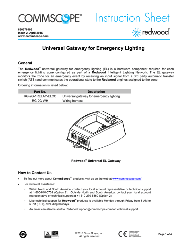
The Redwood universal gateway for emergency lighting (EL) is a hardware component required for each
emergency lighting zone configured as part of a Redwood Intelligent Lighting Network. The EL gateway
monitors the zone for an emergency event by receiving an input signal from a 3rd party automatic transfer
switch (ATS) and communicates the operational state to the Redwood engines assigned to the zone.
Ordering information is listed below:
Part No.
RG-2G-1RELAY-ELCC
RG-2G-WH
Description
Universal gateway for emergency lighting
Wiring harness
®
Redwood Universal EL Gateway
How to Contact Us
•
To find out more about CommScope products, visit us on the web at www.commscope.com/
•
For technical assistance:
®
-
Within North and South America, contact your local account representative or technical support
at 1-800-840-0709 (Option 2). Outside North and South America, contact your local account
representative or technical support at +1 510-270-5360 (Option 2).
-
Live technical support for Redwood products is available Monday through Friday from 8 AM to
5 PM (PST), excluding holidays.
-
An email can also be sent to RedwoodSupport@commscope.com for technical support.
®
© 2015 CommScope, Inc.
All rights reserved
For RoHS Inquiries:
CommScope Inc.
Corke Abbey, Bray
Co. Dublin, Ireland
Attn: Legal Department
Page 1 of 4
860576495
Instruction Sheet
www.commscope.com
Important
•
Do NOT place the EL gateway in a location where it will get hotter than 50°C.
•
When the product is installed in air-handling spaces, such as above some suspended ceilings, the
cabling employed should be suitable under NEC (2008) Article 800.154 and marked accordingly for use
in plenums and air-handling spaces with regard to smoke propagation, such as CMP. The products and
wiring means should be installed in accordance with all applicable local regulations and practices.
•
The EL gateways have been tested by UL to the UL2043 standard which ensures low smoke-emitting
characteristics and suitable fire resistance for equipment that may be installed in environmental airhandling spaces, as described in Article 300.22 of the NEC (2008).
Wiring Diagram
The ATS/UPS used with the Redwood Intelligent Lighting Network emergency lighting solution must contain
isolated contacts that convey the state of the transfer switch. These isolated contacts are sometimes referred to
as auxiliary contacts. The emergency lighting solution will monitor these contacts in order to know the current
state of the ATS primary/preferred (non-emergency) or backup/alternate/battery (emergency) electrical power.
The recommended configuration for the zone contact setting is closed for primary power and open for backup
power, but the zone contact setting can be configured in the emergency lighting solution software as required by
the ATS hardware.
AUX. Contacts
Closed on Preferred
AUX. Contacts
Closed on Alternate
The Redwood universal gateway wiring harness must be used to make the connection to these contacts as
shown in the following wiring diagram. The harness should enter the ATS through a separate knockout than the
one used for preferred or alternate power sources. To test the EL gateway component functionality and wiring,
an electrical switch can be wired between the ATS and the EL gateway.
One EL gateway is specified for each Redwood engine assigned to a zone (see wiring diagram on next page).
The EL gateways are daisy-chained together using universal gateway wiring harnesses and located near the
ATS so that one EL gateway can be connected to the ATS auxiliary switch position contacts. Each EL gateway
is also connected by a low-voltage cable to a port on each Redwood engine assigned to the zone.
Page 2 of 4
www.commscope.com
860576495
Instruction Sheet
IP
Network
Automatic
Transfer
Switch
Connect ATS
switch position
N/C contacts to
Redwood UG
wiring harness
Optional
Test Switch
AC Power
Redwood
Engine
Redwood
Universal
Gateway Emergency
Lighting
Redwood Universal
Gateway Wiring
Harness
Yellow
Yellow
Wht/Blu
Wht/Red
AC Power
Redwood
Engine
Redwood
Universal
Gateway Emergency
Lighting
Redwood Universal
Gateway Wiring
Harness
Yellow
Yellow
Wht/Blu
Wht/Red
Redwood
Universal
Gateway Emergency
Lighting
Redwood Universal
Gateway Wiring
Harness
Yellow
Yellow
Wht/Blu
Wht/Red
..
.
..
..
.
AC Power
Redwood
Engine
Preparation
1. Determine the locations for ATS, EL gateways, and Redwood engines.
Note: The EL gateways should be installed near the ATS so that one can be connected to the ATS
auxiliary switch position contacts and daisy-chained together using universal gateway wiring harnesses.
2. Run low-voltage cable from Redwood engine location to each EL gateway. For low voltage cabling,
use a RJ45 connector wired as T568A or T568B.
Page 3 of 4
860576495
Instruction Sheet
www.commscope.com
Installation Instructions
1. Connect one EL gateway to the ATS auxiliary switch position contacts using the universal gateway wiring
harness contact closure input wires (see below).
Optional: Connect a switch between the EL gateway and ATS to enable testing of the EL gateway
component functionality and wiring as shown in the wiring diagram.
2. Hardwire and daisy-chain together all the EL gateways using the universal gateway wiring harness.
Connect the contact closure input wires to the relay 1 (terminal A) and relay 1 (terminal B) wires. For the
last EL gateway, the relay 1 (terminal A) and relay 1 (terminal B) wires are not connected (see below).
3. Connect each EL gateway to an engine assigned to the zone with RJ45 connectors for category cabling.
4. Secure the EL gateway by mounting it to part of the building structure that does not exceed the mechanical
specifications for the gateway.
Page 4 of 4


