Enpirion® Power Evaluation Board
ER3105DI 500mA Wide VIN
Synchronous Buck Regulator
Evaluation Board User Guide
Description
competing solutions. The evaluation board is
optimized for engineering ease of testing
through programming options, clip leads, test
points and supporting external components.
The ER3105DI and its sister part, the
ER3110DI, share a common printed circuit
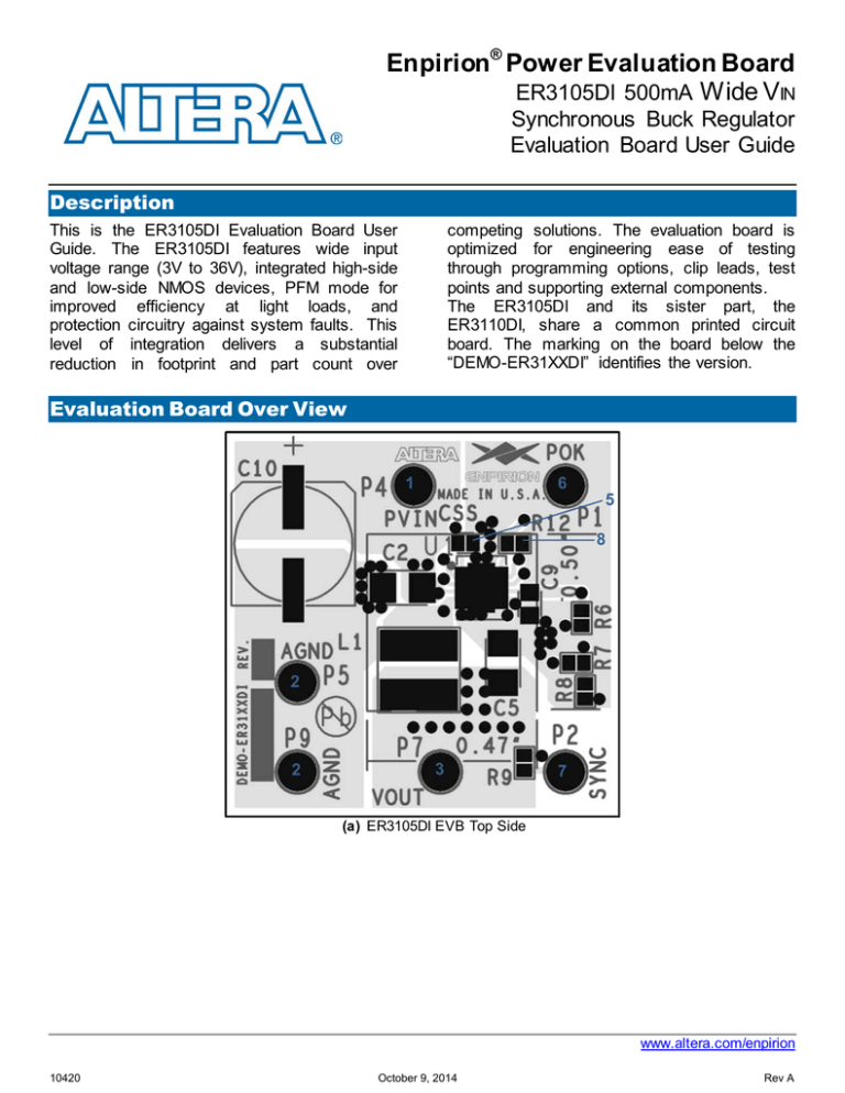
board. The marking on the board below the
“DEMO-ER31XXDI” identifies the version.
This is the ER3105DI Evaluation Board User
Guide. The ER3105DI features wide input
voltage range (3V to 36V), integrated high-side
and low-side NMOS devices, PFM mode for
improved efficiency at light loads, and
protection circuitry against system faults. This
level of integration delivers a substantial
reduction in footprint and part count over
Evaluation Board Over View
1
6
5
8
2
2
3
7
(a) ER3105DI EVB Top Side
www.altera.com/enpirion
10420
October 9, 2014
Rev A
ER3105DI Evaluation Board User Guide
8
4
(b) ER3105DI EVB Bottom Side
Figure 1. ER3105DI Evaluation Board Illustration (Follow instructions on page 2)
Instructions
The numbers in the instructions below correspond
to the numbers in Figure 1. By following the number
sequence below, the device can be turned on by
step 3.
1) PVIN (P4) – Connect a 3V to 36V power
supply on P4. Do not turn the power supply
on until everything is connected correctly.
2) Ground (P5 and P9) – Connect the input
power supply ground to P5 and the output
ground to P9.
3) VOUT (P7) – Connect the load to P7. If the
instructions were followed up to this point,
the power supply may be turned on. To
disable the evaluation board, turn off the
power supply connected in Step 1 and 2.
The device may also be enabled or disabled
by pulling the EN pin high or low,
respectively.
4) Output Voltage Setting – The output
voltage programming resistor R3, depends
on the value chosen for the feedback
resistor R2 and the desired output voltage
VOUT.
Equation
1
describes the
relationship between VOUT and the resistor
values.
𝑅2 ∗ 0.6𝑉
𝑅3 =
(1)
𝑉𝑜𝑢𝑡 − 0.6𝑉
The feedback resistor R2 is chosen as
90.9kΩ. When changing the output voltage
it may also be necessary to change certain
other circuit elements for stability. See
Table 1 for details.
5) Soft Start Capacitor (Css) – If SS is pulled
to AVINO, an internal 2ms timer is selected
for soft-start. For other soft-start times,
simply connect a capacitor from SS to GND.
The soft-start time can be calculated by
Equation 2:
𝑇𝑖𝑚𝑒 (𝑚𝑠) = 𝐶𝑠𝑠 (𝑛𝐹 ) ∗ 0.3
(2)
6) POK (P1) – This is the open drain POK flag,
which is pulled up to AVIN by R1. When
VOUT is over 90% of regulation, POK will
be pulled high to AVIN; otherwise POK is
pulled low internally.
www.altera.com/enpirion, Page 2
10420
October 9, 2014
Rev A
ER3105DI Evaluation Board User Guide
800kHz. For programing the switching
frequency from 300kHz to 2MHz, use
Equation (3). For a default switching
frequency of 500kHz, tie FSW to AVINO
(Remove R12 and install a 0Ω resistor on
R10).
7) SYNC (P2) – SYNC is connected to AVINO
through the R6 (200kΩ) resistor and sets
the device to operate in PWM mode only.
To set automatic PFM or PWM mode,
remove R6 and install a 0Ω resistor on R9.
8) FSW (R10, R12) – The ER3105DI
Evaluation Board operates at adjustable
switching frequency mode, where a resistor
RFSW (R12=120kΩ) is installed from FSW to
GND to set the switching frequency to
𝑅𝑓𝑠𝑤 = 108.75∙ �
1
− 0.2� (𝑘Ω)
F sw(𝑀𝐻𝑧)
Vout
(V)
L1
(µH)
C2
(µF)
R1
(KΩ)
R2
(KΩ)
C4
(pF)
R12
(KΩ)
R3
(KΩ)
12
5
45
22
10
2x22
90.9
90.9
4.75
12.4
22
100
115
120
100
100
3.3
22
2x22
90.9
20
100
120
100
2.5
1.8
22
22
2x22
22
90.9
100
28.7
50
100
22
120
120
100
50
(3)
Table 1: External Components for Adjusting the Output Voltage
www.altera.com/enpirion, Page 3
10420
October 9, 2014
Rev A
ER3105DI Evaluation Board User Guide
Evaluation Board Schematic
www.altera.com/enpirion, Page 4
10420
October 9, 2014
Rev A
ER3105DI Evaluation Board User Guide
Bill of Materials
Designator
Qty
C4
CSS
C7
C3
C9
C1, C2
C5,C6
L1
P4, P7
P5, P9
P1, P2
U1
R3
R12
R2
R6, R7
R1
R8-R11,R15
1
1
1
1
1
2
2
1
2
2
2
1
1
1
1
2
1
5
Description
CAP,SMD,0402,100pF,50V,5%,C0G,ROHS
CAP, SMD,0402,33000pF,16V,10%,X7R,ROHS
CAP,SMD,0402,470pF,50V,10%,X7R,ROHS
CAP,SMD,0603,0.1uF,50V,10%,X7R,ROHS
CAP,SMD,0603, 1uF,16V,10%,X5R,ROHS
CAP,SMD,1206,10uF,50V,10%,X5R,ROHS
CAP,SMD,1206, 22uF,6.3V,10%,X5R,ROHS
COIL-PWR INDUCTOR,SMD,4.8mm,22uH,20%,1.1A,ROHS
CONN-MINI TEST PT,VERTICAL,RED,ROHS
CONN-MINI TEST PT,VERTICAL,BLK,ROHS
CONN-MINI TEST POINT,VERTICAL,WHITE,ROHS
ER3105DI BUCK REGULATOR,12P,DFN,3X4,ROHS
RES, SMD, 0402, 100K, 1/16W, 1%, TF,ROHS
RES,SMD,0402, 120K, 1/16W,1%,TF,ROHS
RES, SMD, 0402, 20K, 1/16W, 1%, TF,ROHS
RES,SMD,0402, 200K,1/16W,1%,TF,ROHS
RES,SMD,0402, 90.9K,1/16W,1%,TF,ROHS
RES,SMD,0402, DNP, DNP, DNP,TF,ROHS
Test Recommendations
To guarantee measurement accuracy, the following precautions should be observed:
1. Make all input and output voltage measurements at the board using the test points provided
(P4 to P7). This will eliminate voltage drop across the line and load cables that can produce
false readings.
2. Measure input and output current with series ammeters or accurate shunt resistors. This is
especially important when measuring efficiency.
3. The board includes a pull-up resistor for the POK signal and ready to monitor the power OK
status at clip lead marked POK.
Contact Information
Altera Corporation
101 Innovation Drive
San Jose, CA 95134
Phone: 408-544-7000
www.altera.com
© 2013 Altera Corporation—Confidential. All rights reserved. ALTERA, ARRIA, CYCLONE, ENPIRION, HARDCOPY, MAX, MEGACORE, NIOS, QUARTUS and STRATIX
words and logos are trademarks of Altera Corporation and registered in the U.S. Patent and Trademark Office and in other countries. All other words and logos identif ied as
trademarks or service marks are the property of their respective holders as described at www.altera.com/common/legal.html. Altera warrants performance of its semiconductor
products to current specifications in accordance with Altera's standard warranty, but reserves the right to make changes to any products and serv ices at any time without
notice. Altera assumes no responsibility or liability arising out of the application or use of any information, product, or service described herein except as expressly agreed to in
writing by Altera. Altera customers are advised to obtain the latest version of device specifications before relying on any published information and bef ore placing orders f or
products or serv ices.
www.altera.com/enpirion, Page 5
10420
October 9, 2014
Rev A

