Laplace transform and RC circuits analysis

Laplace transform and RC circuits analysis
Krzysztof Brzostowski
1 The charging transient
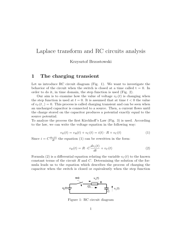
Let us introduce RC circuit diagram (Fig. 1). We want to investigate the behavior of the circuit when the switch is closed at a time called t = 0. In order to do it, in time domain, the step function is used (Fig. 2).
Our aim is to examine how the value of voltage v
C
( t ) is changing when the step function is used at t = 0. It is assumed that at time t < 0 the value of v
C
( t
−
) = 0. This process is called charging transient and can be seen when an uncharged capacitor is connected to a source. Then, a current flows until the charge stored on the capacitor produces a potential exactly equal to the source potential.
To analyze the process the first Kirchhoff’s Law (Fig. 3) is used. According to the law, we can write the voltage equation in the following way: v
E
( t ) = v
R
( t ) + v
C
( t ) = i ( t ) · R + v
C
( t )
Since i = C dv c
( t ) dt the equation (1) can be rewritten in the form:
(1) v
E
( t ) = R · C dv c
( t ) dt
+ v
C
( t ) (2)
Formula (2) is a differential equation relating the variable v
C
( t ) to the known constant terms of the circuit R and C . Determining the solution of the formula leads us to the equation which describes the process of charging the capacitor when the switch is closed or equivalently when the step function
Figure 1: RC circuit diagram
1
Figure 2: The step function
Figure 3: The first Kirchhoff’s Law appears in the diagram’s input.
Generally, trying to find the solution of the differential equation is not easy and can be very challenging task. To make this process easy Laplace’s transform can be used.
Introduced in the previous sections circuits diagram can be relabeled for
Laplace task (4).
Let us define the transient function , which is denoted as H ( s ):
H ( s ) = v
C
( s ) v
E
( s )
(3)
Next step is to determine resultant impedance for the investigated circuit diagram:
H ( s ) =
R
1 sC
+
1 sC
= sRC
1
+ 1
(4)
Figure 4: RC circuit diagram in complex number domain
2
Figure 5: Step response of RC circuit
Figure 6: RL circuit diagram in complex number domain
Now, we can calculate the response of our circuit diagram when switch is closed or (equivalently) step function appears at input: u
C
( s ) = H ( s ) · u
E
( s ) =
1 sRC + 1
·
1 s
=
1 s
− s +
1
1
RC
(5) where
1 is the equivalent of step function in complex number domain .
s
Then, next task is to find the inverse Laplace’s transform in order to determine the charging transient in time domain .
L − 1
{ u
C
( s ) } =
L − 1
{
1 s
− s +
1
1
RC
} (6)
Consequently: u
C
( t ) = u
E
(1 − e
− t
RC
) (7) where u
E in this example is constant. The graphical representation is shown in Fig. 5. It can be seen that RC circuit behaves as the first order object.
2 Exercise
Analyze behavior of the following RL circuit diagram (6) for the step function.
3


