Error Codes
Error codes are indicated by the lit Red LED located
on the front of the tester along with a two digit code
displayed in the LED Readout.
Error
Code
01
02
Required Action
Over Temperature — Turn the tester off and
allow to cool. Prolonged high current usage
can cause overheating as well as damage to
the load under test.
Over Current — Excessive current draw may
be caused by high start-up demand on the
component being tested. Start from 0% and
slowly increase the current. Over Current
can also be caused by failing component or
excessive testing run time.
03
Low Battery — The tester detected low
battery voltage. Check the vehicle’s battery
and/or connections.
04
Ground Jack Inoperable — The tester
detected (at power up) that the ground jack
is open. The tester is still usable but you must
run a separate ground jumper. To correct the
error the tester must be sent in to Hickok /
Waekon for service
05
Quick Start Guide
Timed Out — To protect the vehicle, the
Auto-off time varies with the current.
Specifications
Power Supply
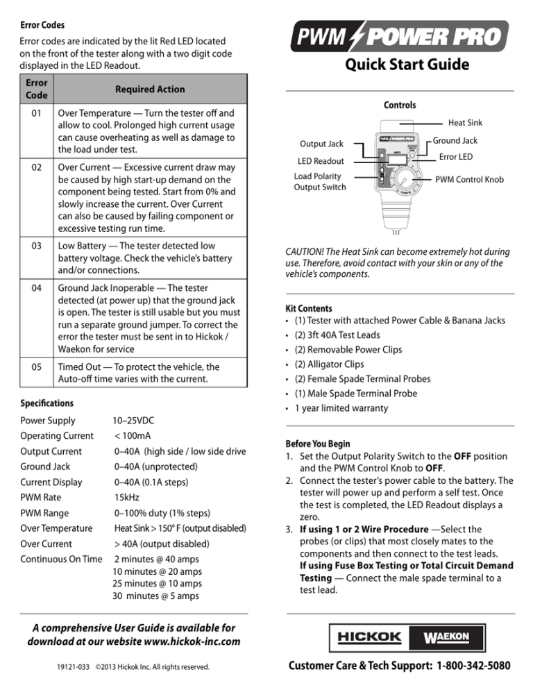
Controls
Heat Sink
Output Jack
LED Readout
Load Polarity
Output Switch
Ground Jack
Error LED
PWM Control Knob
CAUTION! The Heat Sink can become extremely hot during
use. Therefore, avoid contact with your skin or any of the
vehicle’s components.
Kit Contents
• (1) Tester with attached Power Cable & Banana Jacks
• (2) 3ft 40A Test Leads
• (2) Removable Power Clips
• (2) Alligator Clips
• (2) Female Spade Terminal Probes
• (1) Male Spade Terminal Probe
• 1 year limited warranty
10–25VDC
Operating Current
< 100mA
Output Current
0–40A (high side / low side drive
Ground Jack
0–40A (unprotected)
Current Display
0–40A (0.1A steps)
PWM Rate
15kHz
PWM Range
0–100% duty (1% steps)
Over Temperature
Heat Sink > 150° F (output disabled)
Over Current
> 40A (output disabled)
Continuous On Time
2 minutes @ 40 amps
10 minutes @ 20 amps
25 minutes @ 10 amps
30 minutes @ 5 amps
Before You Begin
1. Set the Output Polarity Switch to the OFF position
and the PWM Control Knob to OFF.
2. Connect the tester’s power cable to the battery. The
tester will power up and perform a self test. Once
the test is completed, the LED Readout displays a
zero.
3. If using 1 or 2 Wire Procedure —Select the
probes (or clips) that most closely mates to the
components and then connect to the test leads.
If using Fuse Box Testing or Total Circuit Demand
Testing — Connect the male spade terminal to a
test lead.
A comprehensive User Guide is available for
download at our website www.hickok-inc.com
19121-033 ©2013 Hickok Inc. All rights reserved.
Customer Care & Tech Support: 1-800-342-5080
Tester
Red Test Lead +
OUTPUT
Black Test –
Lead
Component
2 Wire Testing Procedure
1. Plug the red test lead into the output jack and the
black test lead into the ground jack. IMPORTANT! To
avoid possible damage, do not let the tips of the leads
touch once they are connected to the tester.
2. Disconnect the component from the circuit and
connect the positive ( + ) and negative ( – ) leads to
the component per the vehicle’s shop manual.
Vehicle Harness
IMPORTANT! The tester GROUND JACK is
not protected. If connected to the battery’s
positive ( + ) terminal, it will fail and
become inoperable (see Error Code 04).
3. Set the Output Polarity Switch to + and rotate the
PWM Control knob to increase (or decrease) the
amount (%) desired to test the component. The
amount of current the component is drawing is
displayed in the LED Readout.
Note: For reversing motors such as power windows
and locks, reverse the test leads to drive the motor in
the opposite direction.
Tester
1 Wire Testing Procedure
1. Plug the test lead into the output jack.
OUTPUT
Test Lead
Vehicle
Harness
Component
2. Connect the output lead to the component by back
probing the drive side of the component per the
vehicle’s shop manual.
3. Set the Output Polarity Switch to + or – based on the
component’s circuit operation per the vehicle’s shop
manual. Rotate the PWM Control knob to increase
(or decrease) the amount (%) desired to test the
component. The amount of current the component is
drawing is displayed in the LED Readout.
Tester
Fuse Box Testing Procedure
1. Plug the test lead into the output jack.
Test Lead
OUTPUT
Fuse / Relay
Box
Component
2. Remove the fuse (or relay) and connect the output
lead to the component side of the fuse or relay per
the vehicle’s shop manual.
3. Set the Output Polarity Switch to + and rotate the
PWM Control knob to increase (or decrease) the
amount (%) desired to test the component. The
amount of current the component is drawing is
displayed in the LED Readout.
Total Circuit Demand Testing Procedure
1. Plug the test lead into the output jack.
2. Remove the fuse (or relay) and set the Output
Polarity Switch to + and rotate the PWM Control
knob to 100%.
After You Complete All Tests
Make note of the results and refer to the specifications
listed in the vehicle’s shop manual to determine the
course of action needed for repairs.
3. Connect to the component side of the suspect circuit
fuse or relay with all of the component(s) turned on
(or off, as desired). Determine the demand by reading
the amps displayed in the LED Readout

