RADIANT HEATING AND
COOLING SYSTEMS
STAINLESS-STEEL
MANIFOLD
INSTALLATION GUIDE
Stainless-steel Manifold
Installation Guide
Stainless-steel Manifold Installation Guide
Published by Uponor North America
5925 148th Street West
Apple Valley, MN 55124 USA
Phone: 800.321.4739
Fax: 952.891.2008
www.uponorpro.com
© 2014 Uponor North America
All Rights Reserved.
First Edition April 2014
First Printing April 2014
Printed in the United States of America
Stainless-steel
Manifold Installation Guide
Overview
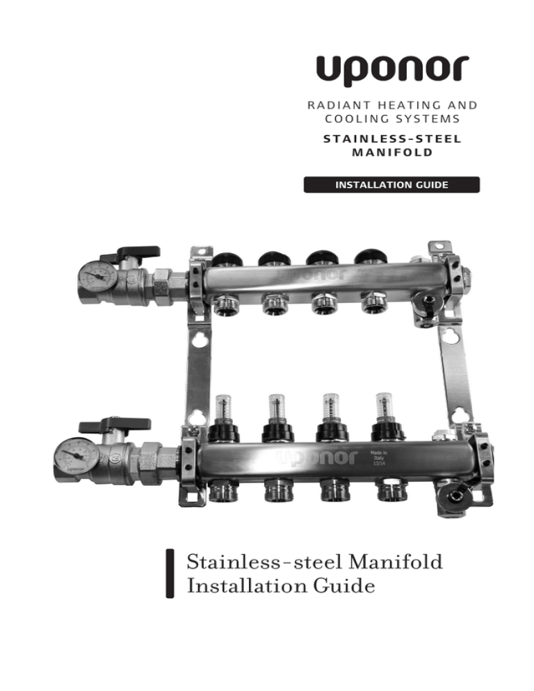
Featuring 2 through 8, 10 and 12 loops, the Uponor Stainless-steel
Manifold comes fully assembled with flow meters, temperature gauges,
ball valves and NPT connections.
Note: The valve body with the preassembled flow meters is the supply
manifold; the valve body without the flow
Thermal Actuator, Two-wire (A3020416)
or Thermal Actuator, Four-wire (A3010522)
meters is the return manifold.
Spacer Ring VAIO for white thermal
actuator (A2771060)
ProPEX Brass Male Threaded Adapter (¾" x ¾" NPT LF4527575,
¾" x 1" NPT LF4527510, 1" x ¾" NPT LF4521075, 1" x 1" NPT LF4521010)
Stainless-steel Manifold Isolation Valve
Body, replacement part (A2771030)
Stainless-steel Manifold Temperature Gauge, Set of 2 (A2771050)
Stainless-steel Manifold Supply
and Return 1¼" NPT Ball Valve
with Temperature Gauge,
set of 2 (A2771252)
or
Stainless-steel Manifold Supply
and Return 1" NPT Ball Valve
with Temperature Gauge,
Set of 2 (A2771251)
Mounting Bracket for Stainless-steel Manifold,
1¼" replacement part, set of 2 (A2771011)
or
Mounting Bracket for Stainless-steel Manifold,
1" replacement part, set of 2 (A2771010)
Stainless-steel Manifold Flow Meter 2 GPM Valve
Body, replacement part (A2771021)
or
Stainless-steel Manifold Flow Meter 1.5 GPM Valve
Body, replacement part (A2771020)
Stainless-steel Manifold
Installation Kit (A2771070)
TruFLOW Classic Manifold
Offset Union (A2620045)
or
TruFLOW Classic Manifold
Elbow Union (A2620090)
MCC Press Fitting Assembly
(½" D4020500, 5/8" D4020625)
ProPEX Fitting Assemblies (3/8" Q4020375, ½" Q4020500,
5
/8" Q4020625, ¾" Q4020750)
MCC Tubing Compression Fitting Assemblies (½" D4120500, 5/8" D4120625)
QS-Style Compression Fitting Assemblies (5/16" A4020313, 3/8" A4020375, ½" A4020500, 5/8" A4020625)
Stainless-steel Manifold Installation Guide
3
Mounting Manifold to a Wall
1. Fasten the manifold to a wall using a rigid anchor and
mounting screws (included).
Mounting Manifold Inside a Wall Cabinet
1. Insert the cage nuts (included) in the mounting rail.
2. Align the manifold bracket holes with the cage nuts in the rail and loosely
fasten with bolts (included).
3. Slide the manifold into the desired position and tighten the bolts.
Note: For wall cabinet mounting instructions, refer to the Uponor Manifold
Wall Cabinet Instruction Sheet.
Note: When installing the Stainless-steel Manifold with 10 or 12 loops,
adjust mounting bracket spacing for proper fit on cabinet rail.
Distribution Pipe
The Stainless-steel Manifold Assembly comes standard with loosley fitted
Manifold Supply Ball Valves. Follow the below direction to install a
NPT transition fitting, manifold elbow union, or manifold offset union
connection. Refer to the Uponor Product Catalog for fitting information.
•• Stainless-steel Manifold Supply and Return 1" NPT Ball Valve with
Temperature Gauge, set of 2 (A2771251) comes standard on all
1" Stainless-steel Manifold assemblies and 11⁄4" manifolds with
2 through 7 loops.
•• Stainless-steel Manifold Supply and Return 11⁄4" NPT Ball Valve with
Temperature Gauge, set of 2 (A2771252) comes standard on all 11⁄4"
Manifold 8, 10 and 12 loops.
Note: Make NPT connections prior to R32 union connections to insure
proper orientation.
When using NPT Transition Fittings
1. Apply pipe dope or Teflon tape to NPT X ProPEX® transition fitting
threads into FNPT ball valve thread.
2. Adjust Manifold Supply and Return Ball Valve to proper orientation
and tighten.
Note: An NPT x NPT reducing coupling may be required to adapt 1" or 11⁄4"
FNPT thread-on ball valve to ditribution piping (supplied by other).
4
www.uponorpro.com
When using Manifold Elbow or Offset Union
Connections (A2620090 or A2620045)
1. Remove the loosely fitted Manifold Supply and Return Ball Valves.
2. Thread Manifold Elbow Union (A2620090) or Manifold Offset Union
(A2620045) connection into the Stainless-steel Manifold Assembly’s R32
union connection with a flat gasket.
3. Thread Manifold Supply and Return Ball Valve (A2771251 or A2771252)
into the4R32 union connection on the
3 Manifold Elbow or Offset
2 Union
Connection with a flat gasket.
1
4. Apply pipe dope or teflon tape to NPT x ProPEX transition fitting threads
and thread into FNPT ball valve thread.
5. Adjust Manifold Elbow Union or Manifold Offset Union connection as
well as the Manifold Supply and Return Ball Valve to proper orientation
and tighten.
1
4
5
2
3
4
Stainless-steel Manifold Installation Guide
5
Connecting Tubing to the Manifold
Connect the tubing to the manifold using either the ProPEX connection method or
QS-style fittings. Refer to the Uponor Product Catalog for fitting information.
ProPEX Connections
1
1. Use a PEX Cutter (E6081125, E6081128
or E6081501) to square-cut the tubing
perpendicular to the tubing length.
Note: Do not use a saw or similar cutting
tool as shavings may clog the manifold valves.
2. Slide the ProPEX Ring over the end of the tubing
until it reaches the stop edge.
Square-cut the Tubing
Note: Ensure the ring is dry and free of grease to
prevent it from sliding out of place.
2
3. Attach the proper size ProPEX Expander Head onto
the expander tool and expand the tubing with the
proper number of expansions (see Table 1).
Slide ProPEX Ring onto Tubing
4
4. After expanding the tubing and ring, immediately
remove the expander tool and slide the tubing over
the fitting until the tubing reaches the stop on the
fitting. Hold the tubing in place for two or three
seconds to ensure a proper seal.
QS-style Fittings
1. W
hen connecting the tubing with a QS-style fitting,
make sure the tubing is pushed all the way into the
fitting and tighten the fitting with a wrench.
Note: Do not over-tighten or twist the tubing.
Expand the Tubing
2
2. If you need to remove a QS-style fitting from the
tubing, use a screwdriver to open the clamp ring
and remove the insert.
Tubing Milwaukee® ProPEX Tool Uponor ProPEX Tool
Size
M12
M18
Manual 100 & 150
m
1m
Use a Screwdriver to Open
Clamp Ring and Remove Fitting
6
/"
/"
3/4"
3 8
1 2
8
5
9
9
6
8
5
4
9
7
4
9H*
Table 1: Recommended Number of ProPEX Expansions
*H refers to Uponor H-series expander heads.
www.uponorpro.com
Filling and Purging the Manifold
To ensure proper system performance, it is important to fill and purge the
system at the boiler or at the manifold. Refer to the following instructions to
fill and purge at the manifold.
1. Connect a hose from a faucet to the fill valve on the supply manifold.
2. Connect a separate drain hose to the return manifold and place the other
end into a large bucket or drain.
3. Remove the flow meter locking cover.
4. Close all valves on the manifold (both supply and return) as well as the ball
valves (A2771251 or A2771252) installed on the supply and return lines.
5. Use the square tool on the cap of the hose bib fill port to open the fill
3
2
valves 4on the supply and return manifold.
1
6. Open the valves for the first loop on the manifold.
7. Fill the loop with water. Continue the filling process until the water is clear
with no bubbles.
8. Repeat Steps 4 through 6 to fill and purge each manifold loop.
9. Replace the flow meter locking cover.
open
close
6
close
close
close
close
4
2
open
3
5
close
close
close
close
close
1
Stainless-steel Manifold Installation Guide
7
Pressure Testing
To ensure the system is installed correctly and operating properly,
it is important to pressure test the system. There are several options
to pressure test a system, including air and water. However, air provides
a much more rigorous test.
1. To ensure all valves are working accurately, open and close all valves
twice. Make sure all manifold isolation and flow valves are open.
N
ote: Manifold Supply and Return Ball Valves should be closed
during the pressure test procedure.
4
2. Connect the Uponor Manifold Pressure Test Kit (E6122000) or other
pressure test device. Uponor recommends a test pressure of 3 times
the operating pressure, or at least 40 psi.
3
2
Note: Maximum pressure when testing with air should not exceed 100 psi.
3. Visually check for leaking and monitor the pressure for the duration
specified by local code. (A typical pressure test can range from
2 to 24 hours.)
4. If there is no reduction in pressure, the system is regarded as sealed.
5. After completing the pressure test, set the operation pressure.
close
open
open
open
open
open
close
8
www.uponorpro.com
1
Balancing the Manifold
Balancing the manifold helps to ensure proper system performance.
1. Ensure the system is operating and water is flowing through the manifold.
4
3
2. Remove the flow meter’s locking
cover.
2
1
3. Turn the balancing valve to obtain the desired flow.
Note: Visually check the flow meter window to ensure proper flow.
4. Replace the flow meter cover to set the valve position and push
it down into the locked position.
2
3
4
Stainless-steel Manifold Installation Guide
9
Notes
10
www.uponorpro.com
Notes
Stainless-steel Manifold Installation Guide
11
StainlessSteelMfld_InsG_H479_0414, Copyright © 2014 Uponor. Printed in the United States
Uponor, Inc.
5925 148th Street West
Apple Valley, MN 55124 USA
Tel: 800.321.4739
Fax: 952.891.2008
Uponor Ltd.
2000 Argentia Rd., Plaza 1, Ste. 200
Mississauga, ON L5N 1W1 CANADA
Tel: 888.994.7726
Fax: 800.638.9517
www.uponorpro.com

