LabDITCS
Laboratory - Digital Imager Timing Certification System
General Description:
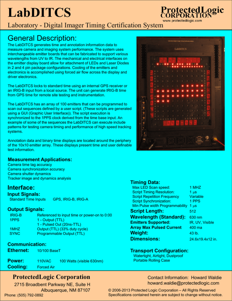
The LabDITCS generates time and annotation information data to
measure camera and imaging system performance. The system uses
interchangeable emitter boards that can be fabricated to support various
wavelengths from UV to IR. The mechanical and electrical interfaces on
the emitter display board allow for attachment of LEDs and Laser Diodes
in 2 and 4 pin package configurations. Cooling of the emitters and
electronics is accomplished using forced air flow across the display and
driver electronics.
The LabDITCS locks to standard time using an internal GPS receiver or
an IRIG-B input from a local source. The unit can generate IRIG-B time
from GPS time for remote site testing and instrumentation.
The LabDITCS has an array of 100 emitters that can be programmed to
scan out sequences defined by a user script. (These scripts are generated
using a GUI (Graphic User Interface)). The script execution is
synchronized to the 1PPS clock derived from the time base input. An
example of some of the sequences the LabDITCS can execute include
patterns for testing camera timing and performance of high speed tracking
systems.
Annotation data and binary time displays are located around the periphery
of the 10x10 emitter array. These displays present time and user definable
test information.
Measurement Applications:
Camera time tag accuracy
Camera synchronization accuracy
Camera shutter dynamics
Tracker image and dynamics analysis
Timing Data:
Interface:
Max LED Scan speed:
Script Timing Resolution:
Script Repetition Frequency
Script Synchronization:
Min Pulse width Programmability
Input Signals:
Standard Time Inputs
GPS, IRIG-B, IRIG-A
Output Signals:
IRIG-B
1PPS
1MHZ
SYNC
Referenced to input time or power-on to 0:00
1 - Output (TTL)
1 - Pulsed Out (20ns-TTL)
Output (TTL) (33% duty cycle)
Programmable Output (TTL)
Communication:
10/100 BaseT
Ethernet:
Power:
Cooling:
110VAC
100 Watts (visible 630nm)
Script Length:
Wavelength (Standard):
Emitters Supported:
Array Max Pulsed Current
Weight:
Dimensions:
1 MHZ
1 s
Variable
1 PPS
1 s
512
630 nm
IR, UV, Visible
400 ma
43 lb.
24.6x19.4x12 in.
Transport Configuration:
Watertight, Airtight, Dustproof
Portable Rolling Case
Forced Air
ProtectedLogic Corporation
2715 Broadbent Parkway NE, Suite H
Albuquerque, NM 87107
Phone: (505) 792-0892
Contact Information: Howard Waldie
howard.waldie@protectedlogic.com
© 2006-2013 Protected Logic Corporation – All Rights Reserved
Specifications contained herein are subject to change without notice.
LabDITCS
Laboratory - Digital Imager Timing Certification System
Support Software
The GUI is on a remote computer that communicates with the LabDITCS using the
Ethernet interface. The completed scripts are downloaded to the unit using the
standard TCP/IP FTP. The unit can reside on any network that will supply 10/100
BaseT TCP/IP support or can operate directly with a single computer using a crossover cable. The IP address is configurable to allow it to reside on existing networks.
Settings for the display boards can be changed to
allow different types of emitter boards and maximum
limits for current sent to the emitters.
The LabDITCS software allows setting or clearing of
annotation displays using keyboard and mouse point
and click operations. The array display is programmed
separately using a script generator screen shown
below.
The array allows the user to program the script (Sequence, On Time, Off
Time and Intensity of the individual LEDs) using point and click as well as
data entry methods. The script time resolutions are in increments of
microseconds with a range of 1 to more than one second. The GUI allows
forward and backward stepping and playing of the script being generated on
the display.
The final project and script can be saved to disk and/or downloaded to the
LabDITCS for execution.
The LabDITCS executes the array script continuously restarting the script
immediately after the last entry is completed. The 1 PPS signal is used to
re-synchronize the script to GPS time at the beginning of each second. The
GUI assists the operator in writing scripts that will align with the 1PPS.
ProtectedLogic Corporation
2715 Broadbent Parkway NE, Suite H
Albuquerque, NM 87107
Phone: (505) 792-0892
© 2006-2013 Protected Logic Corporation – All Rights Reserved
Specifications contained herein are subject to change without notice.
LabDITCS
Laboratory - Digital Imager Timing Certification System
Camera set to 1/60th second exposure
The figure to the left shows the LabDITCS operating in
manual mode without a timing source input. This mode
allows measurement in areas where IRIG or GPS is not
available. In this mode, the LabDITCS will generate a
reference IRIG-B output to attach to the camera being
tested.
The left 16 segment display shows the default date and the
upper 16 segment display shows the time formatted in HRMIN-SEC-sub-seconds which represents the time since
power on. The last 4 digits on the upper display increment
every 100 microseconds and are phase locked to the
derived 1pps clock.
Camera set to 1/250th second exposure
The upper photo shows an image taken using a
handheld camera. The LabDITCS is set to sequence
(left to right and top to bottom) the array diodes every
1000 microseconds. By counting the illuminated LEDs
during the exposure (16 to 17) the measured exposure
time can be calculated as:
Min = 1/(17*.001) = 58.2 fps
Max = 1/(16*.001) = 62.5 fps
The measurement accuracy can be improved by
decreasing the diode on time thereby increasing the
number of diodes illuminated in the image.
The Photo to the right was taken at 1/250th second
shutter speed with the same script executing as seen
on the upper photo. The image intensity decrease, due
to the shorter exposure, can be seen. Five array diodes
are visible with the first slightly dimmer, while the last is
significantly dimmer. The analysis of this image would
result in 4 diodes being illuminated resulting in a
(1/(4*.001) shutter time. The GPS antenna was
attached and the GPS time is being displayed on the
date and time displays.
ProtectedLogic Corporation
2715 Broadbent Parkway NE, Suite H
Albuquerque, NM 87107
Phone: (505) 792-0892
© 2006-2013 Protected Logic Corporation – All Rights Reserved
Specifications contained herein are subject to change without notice.
LabDITCS
Laboratory - Digital Imager Timing Certification System
The LabDITCS is controlled through the Ethernet using TCP/IP packet and FTP communications. The figure
shows the normal operational configuration using a laptop computer running Windows. The software will operate
on the Windows NT/2000/XP environments. Linux and Mac environments are available as options. An external
monitor and keyboard (not shown) can be attached to the LabDITCS for maintenance and monitoring functions.
Who is ProtectedLogic?
ProtectedLogic Corporation is a small business founded in 2004 to define and design special purpose prototypes and
move them to production for both military and commercial systems. ProtectedLogic designs hardware and software to
allow complete turn-key products. The company develops systems with embedded processors and FPGAs. It uses
VHDL as it’s core component hardware design language and C as it’s core embedded control software language. It
has a proprietary library of IP (Intellectual Property) that is used to shorten the design cycles of products. Because the
company is a small business, it can respond to customer needs with minimal delay and lower costs. ProtectedLogic
has strategic partners that perform manufacturing services such as PCB assembly and mechanical fabrication.
F20130213
ProtectedLogic Corporation
2715 Broadbent Parkway NE, Suite H
Albuquerque, NM 87107
Phone: (505) 792-0892
© 2006-2013 Protected Logic Corporation – All Rights Reserved
Specifications contained herein are subject to change without notice.


