Building a simple seismometer
Seismometers operate on the principle of inertia, i.e. a body at rest will tend to remain that way
unless a force is applied to make it move. An ideal seismometer would be a mass floating just
above the ground. When the ground moves (due to the vibrations caused by an earthquake) the
mass remains stationary (since it is experiencing no force to make it move), we then directly
measure the relative motion between the ground and the floating mass which will tell us precisely
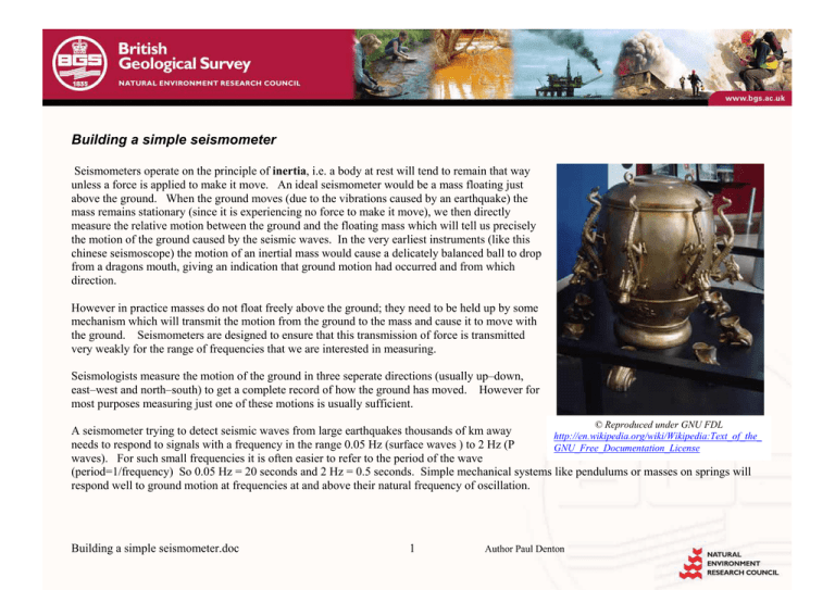
the motion of the ground caused by the seismic waves. In the very earliest instruments (like this
chinese seismoscope) the motion of an inertial mass would cause a delicately balanced ball to drop
from a dragons mouth, giving an indication that ground motion had occurred and from which
direction.
However in practice masses do not float freely above the ground; they need to be held up by some
mechanism which will transmit the motion from the ground to the mass and cause it to move with
the ground. Seismometers are designed to ensure that this transmission of force is transmitted
very weakly for the range of frequencies that we are interested in measuring.
Seismologists measure the motion of the ground in three seperate directions (usually up–down,
east–west and north–south) to get a complete record of how the ground has moved. However for
most purposes measuring just one of these motions is usually sufficient.
© Reproduced under GNU FDL
A seismometer trying to detect seismic waves from large earthquakes thousands of km away
http://en.wikipedia.org/wiki/Wikipedia:Text_of_the_
needs to respond to signals with a frequency in the range 0.05 Hz (surface waves ) to 2 Hz (P
GNU_Free_Documentation_License
waves). For such small frequencies it is often easier to refer to the period of the wave
(period=1/frequency) So 0.05 Hz = 20 seconds and 2 Hz = 0.5 seconds. Simple mechanical systems like pendulums or masses on springs will
respond well to ground motion at frequencies at and above their natural frequency of oscillation.
Building a simple seismometer.doc
1
Author Paul Denton
Simple seismometers
Imaginary effective
suspension point
For a simple pendulum of lengh l the natural period of oscillation T
T = 2π l / g
α
Where g is the acceleration due to gravity (9.8m/s²)
For a pendulum of length 1m this gives T~2 seconds (about the period
of a pendulum in a grandfather clock). To design a simple pendulum
with a natural period of 20 seconds we would need a pendulum length of
~100 m.
However if we adjust the suspension system to that of a ‘garden gate’ or
‘Lehman pattern’ where a horizontal boom rotates about a two point
suspension we can adjust the effctive length of the resulting system by
adjusting the angle of suspension. In this case the effective length of the
pendulum is l/sin(α) so the natural period of the system T becomes
effective
pendulum
length
Suspension wire
Pivot point
Rigid frame
Mass
T = 2π l / g sin(α )
α
In this way it is relatively easy to design a seismometer with a
reasonable sized boom (0.5 m) that has a natural period of 20 seconds by
slightly tilting the system with an angle of 0.3 degrees (this corresonds
to tilting one end of the seismometer by ~2 mm)
Simplified schematic of a simple seismometer (with the angle of
tilt greatly exaggerated)
Building a simple seismometer.doc
2
Author Paul Denton
SEP school seismometer system
The SEP seismometer system is a simple horizontal motion
seismometer. It is :
• simple in principle
• open in construction so that individual components can
be identified
• adjustable in natural period (10–20 seconds)
• adjustable in damping factor
• sensitive enough to detect signals from M6.5
earthquakes anywhere in the world (20–30 per year)
• cheap enough for schools to purchase.
Suspension
wire
Electromagnetic
motion detector
Mass
Pivot point
It comes complete with an electronics box
• wideband amplifier (x 100, x 200 or x 500)
• bandpass filters between 0.0166 Hz and 5Hz
• 16-bit digitiser at 20 samples/sec
Magnetic
damping
system
This unit can then be connected to a PC to record and analyse
the data (see datasheet on Amaseis software)
Building a simple seismometer.doc
3
Author Paul Denton
Vertical seismometers
At its simplest a vertical seismometer consists of a mass suspended on a spring. The natural
frequency of such a system depends on the size of the mass and the spring constant k of the spring,
(where k is determined by plotting a graph of force F required to stretch the spring against the
extension x produced and measuring the slope of that graph). Lower frequencies can be made by
using larger masses or springs with lower spring constants.
Three component data
In practice such a system is very susceptible to horizontal motion (it acts like a simple pendulum).
Usually a pivot or hinge system is employed to constrain the mass to move only in the vertical
plane, this then also gives the possibility of using angled spring systems to create longer period
systems.
spring
Magnet
acts as
a mass
Knife
edge
pivot
One such design is the
‘Lacoste’ suspension
system which can easily be
made to have a natural
period of 2 seconds or more.
Coil produces a
voltage when the
magnet moves
Building a simple seismometer.doc
4
Author Paul Denton
In order to faithfully record the actual motion
of the ground in 3D seismologists
need to use three separate sensors each recording
the vibrations in different direction. These
are usually orientated:
Z component measuring up–down motion
E component measuring east–west motion
N component measuring north–out motion.
Vector addition of these data streams allows
reconstruction of the motion in any direction.
Detecting the motion
Once we have a mechanical system in which the motion of an inertial mass moves relative to the ground (and hence the seismometer frame)
when a seismic wave passes we need some method of detecting and recording this relative motion.
Historically this motion was recorded by pens moving against a rotating drum. There would
be a simple lever system connecting the mass to a pen which would mechanically amplify
the motion of the mass and the paper drum would rotate with a clockwork mechanism that
would enable users to determine the time at which a seismic wave had arrived (to within a
few tens of seconds).
However the sensitivity and dynamic range of these systems was very limited and they were
quickly superseded by electromechanical systems in which the motion of the mass was
converted to a voltage and the voltage was amplified before causing a pen to make marks on
a rotating drum. This also allowed the recording system to be located away from the sensor,
by using radio or telephone line links this analogue voltage signal could be transmitted
hundreds or thousands of kilometres to a central laboratory where seismic data from a whole
network of seismic stations could be recorded and analysed together.
© Reproduced courtesy of U.S. Geological Survey
Nowadays the seismic signal is digitised (usually into 16 bit or 24 bit binary code) with the
data being recorded and analysed by computer. This enables seismologists to use the
internet to exchange data in realtime and create vast ‘virtual networks’ of seismic stations
that span the globe and be automatically analysed to provide near instantaneous warnings
after large events.
Seismic traces being recorded onto
rotating paper charts (helicorders)
Building a simple seismometer.doc
5
Author Paul Denton
Detecting the motion
The principle of electromagnetic induction used in a seismometer is the same as that of a
loudspeaker (in reverse). The relative motion between a magnet and a coil (one of which is
attached to the inertial mass and one is attached to the frame) generates a voltage in the coil that is
proportional to the velocity of the relative motion.
The magnitude of the voltage is also proportional to the strength of the magnet used and the
number of turns in the coil.
S
N
Building a simple seismometer.doc
In practice either the magnet or the coil can be attached to the inertial mass (in commercial
systems the magnet is itself often used as the inertial mass)
6
Author Paul Denton
Damping
Lightly damped seismometer signal
2
•
Amplitude
1
•
0
0
10
20
30
40
•
-1
•
-2
Time (seconds
Near critically damped signal
•
4
Amplitude
2
0
50
60
70
Simple mechanical seismometers will have a natural frequency
of oscillation at which they resonate.
If we try to record a signal that contains components close to
this natural frequency then the seismometer will resonate.
We can prevent this resonance by applying a damping force to
the motion of the inertial mass.
This can be done with a simple dashpot (an oil-filled pot with a
paddle in attached to the boom). This produces a force due to
viscous resistance that opposes the motion and is proportional
to the speed of the motion.
We can also use a magnetic damping system where a
conducting plate is attached to the moving boom which moves
in a static magnetic field, this produces strong eddy currents in
the conducting plate when the boom moves, these eddy
currents produce their own magnetic field which opposes the
static field. The end result is a force that opposes the motion
and is proportional to the speed of the motion.
-2
-4
Time (seconds
Building a simple seismometer.doc
7
Author Paul Denton
Weight drop test
A simple vertical seismometer was constructed using a wooden boom, a Stanley knife blade hinge, an magnet and a home wound coil. The coil
is connected directly to a PC soundcard for recording. Suitable sound recording software is AUDACITY which is free and can be downloaded
from http://audacity.sourceforge.net/
This sensor has a natural period of about 2 seconds. It is unsuitable for
recording earthquake signals since the wooden boom will experience
shrinkage and warping with changes in temperature and humidity.
Recording seismic signals with soundcards can be problematic,
soundcards generally have a high-pass filter set at 20 Hz. Seismic
signals generated by dropping a weight on the floor (try using a 4 kg bag
of sand tightly bound) will have a dominant frequency of about 100 Hz.
A simple seismometer like the one illustrated will respond to these high
frequencies without any damping required (the 20 Hz high pass filter on
the soundcard will remove any signals close to the natural period of the
system at about 0.5 Hz).
Building a simple seismometer.doc
8
Author Paul Denton
Simple experiments with simple seismometers
A simple homemade seismometer connected to a PC soundcard can be used to carry out a number of simple experiments to investigate how the
amplitude and timing of signals recorded varies with different sources. For these experiments a standard weight (4 kg of sand tightly bound in
a strong bag) was used and the data was recorded using the free Audacity sound recording software.
25
0.1
Peak-peak amplitude
20
Amplitude
0.05
0
15
10
5
-0.05
0
0
-0.1
0
5
10
15
20
25
30
0.5
1
1.5
35
2
2.5
3
3.5
distance (m)
Time (sec)
A weight dropped 1m at different distances from the sensor shows how the amplitude of the signal decays with distance in a non-linear way.
Building a simple seismometer.doc
9
Author Paul Denton
Another simple experiment is to keep the distance between the weight drop and the sensor fixed and to vary the height of the weight-drop (and
hence the energy)
20
peak-peak amplitude
0.1
amplitude
0.05
0
15
10
5
-0.05
0
0
-0.1
0.5
1
1.5
2
drop height (m)
time
The results of this experiment indicate that the amplitude of the recorded signal is proportional to the height of the weight-drop.
Unless otherwise stated all materials are BGS © NERC. All rights reserved.
Building a simple seismometer.doc
10
Author Paul Denton
2.5


