Polyphase transformer arrangements with reduced kVA capacities
advertisement

Polyphase Transformer Arrangements With Reduced kVA Capacities For Harmonic
Current Reduction in Rectifier Type Utility Interface
Sewan Choi'
Annette R. von Jouanne'
Prasad N. Enjeti'
Power Electronics Laboratory'
Department of Electrical Engineering
TexasA & M University
College Station, Texas 77843-3128
Tel: (409) 845-7466
Fax: (409) 845-6259
IraL Pitel"
Magna-Power Electronics"
85 Fulton st.
Boonton, NJ 07005
Tel: (201) 263-001 7
Fax: (201) 263-1928
Abstract
In this paper polyphase transformer arrangements
with reduced AVA capacities are presented for harmonic
current reduction in high power rectifier utility interface
systems. Based on the concept of an autotransformer, a
proposed twelve-pulse redfier system is realized with a
resultant kVA rating of 0.18P0 @U). In this arrangement
the rectifier diodes each conduct for 120 degrees per cycle
and thefiflh and seventh harmonics are absent from the
utility input line current. In the second scheme an
eighteen-pulse rectifier is realized with the AVA rating of
0.16P0 @U), rectifier diode conduction of 120 degrees per
cycle andfiph, seventh, eleventh and thirteenth harmonic
cancellation in the utility line currents. Additional
applications for the proposed polyphase transformer
arrangements include twelve and eighteen-pulse systems
feeding multiple six-pulse nonlinear loah, such as ac
motor drives, with an appropriate phase shifl, and this
arrangement substantially reduces the utility line current
harmonics. For example, it is shown that the fiflh and
seventh harmonics generated by two separate six-pulse
nonlinear loads are subtracted, and this contributes to
reduced distortion.
Simulation results verifiing the
proposed concept are presented.
i
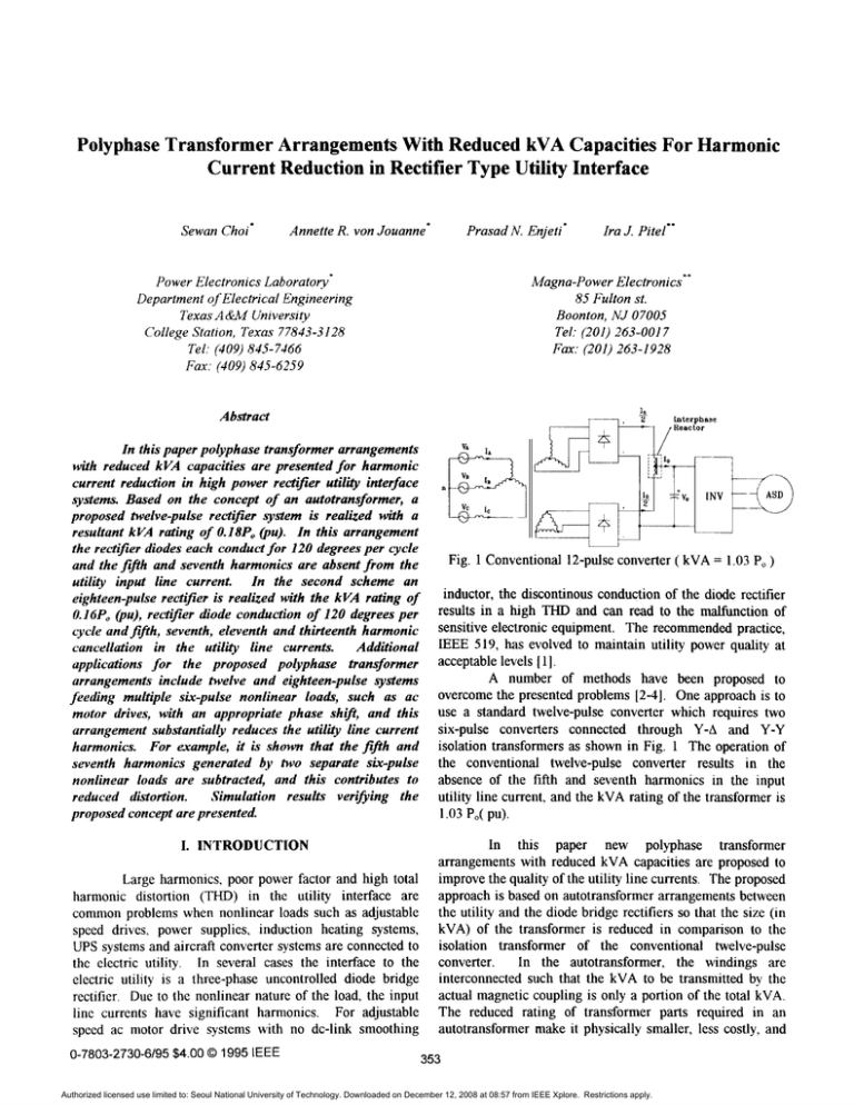
Fig. 1 Conventional 12-pulse converter ( kVA = 1.03 P, )
inductor, the dscontinous conduction of the diode r e c ~ e r
results in a high THD and can read to the malfunction of
sensitive electronic equipment. The recommended practice,
IEEE 519, has evolved to maintain utility power quality at
acceptable levels [ 11.
A number of methods have been proposed to
overcome the presented problems [2-41. One approach is to
use a standard twelve-pulse converter whch requires two
six-pulse converters connected through Y-A and Y-Y
isolation transformers as shown in Fig. 1 The operation of
the conventional twelve-pulse converter results in the
absence of the fifth and seventh harmonics in the input
utility line current, and the kVA rating of the transformer is
1.03 Po(pu).
I. INTRODUCTION
Large harmonics, poor power factor and high total
harmonic distortion (THD) in the utility interface are
common problems when nonlinear loads such as adjustable
speed drives. power supplies, induction heating systems,
UPS systems and aircraft converter systems are connected to
the electric utility. In several cases the interface to the
electric utility is a three-phase uncontrolled diode bridge
rectifier. Due to the nonlinear nature of the load, the input
line currents have significant harmonics. For adjustable
speed ac motor drive systems with no dc-link smoothing
0-7803-2730-6195 $4.000 1995 IEEE
In this paper new polyphase transformer
arrangements with reduced kVA capacities are proposed to
improve the quality of the utility line currents. The proposed
approach is based on autotransformer arrangements between
the utility and the diode bridge rectifiers so that the size (in
kVA) of the transformer is reduced in comparison to the
isolation transformer of the conventional twelve-pulse
converter. In the autotransformer, the windings are
interconnected such that the kVA to be transmitted by the
actual magnetic coupling is only a portion of the total kVA.
The reduced rating of transformer parts required in an
autotransformer make it physically smaller, less costly, and
353
Authorized licensed use limited to: Seoul National University of Technology. Downloaded on December 12, 2008 at 08:57 from IEEE Xplore. Restrictions apply.
I
U
transformer. The winding configuration of an interphase
reactor is shown in Fig. 2 (b). The diodes in each bridge
rectifier conduct for 120 degrees per cycle, and the r e c a e r
input currents (Ia*,Iw,L-as well as I..., I,,.., and I,-) consist of
the six-pulse characteristic harmonics. The autotransformer
bank between the utility and the rectifiers acts like a passive
filter eliminating the fifth and seventh harmonics in the line
current of the utility interface by introducing a 30 degree
phase shift.
P
A. Delta-Type Autotransformer Connection
5 s>
(b)
Fig. 2 (a) Proposed twelve-pulse approach employing the
autotransformer with kVA rating of 0.18 Po @U)
(b) Winding configuration of interphase reactor
higher efficiency than conventional transformers [6]. Fig. 2
(a) shows the proposed twelve-pulse rectdier arrangement.
To ensure the independent operation of two rectifier groups,
two interphase reactors, which are relatively small in size(
0.066 Po@U) ) , become necessary. With this arrangement
the rectifier diodes conduct for 120 degrees per cycle and the
fifth and seventh harmonics are absent from the input line
current.
The same concept can be extended to realize an
eighteen-pulse system (Fig. 7 (a)) in whch the fifth, seventh,
eleventh and hrteenth harmonics in the utility input line
currents are canceled with the kVA rating of 0.16 Po @U).
Additional applications for the proposed polyphase
transformer arrangements include twelve and eighteen-pulse
systems feeding multiple six-pulse nonlinear to substantially
reduce the input harmonics. For example, it is shown that
the fifth and seventh harmonics generated by two separate
six-pulse nonlinear loads ( Fig. 8) are subtracted. Further, in
the case of three separate six-pulse nonlinear loads, the fifth,
seventh, eleventh and thirteenth harmonics are subtracted.
Several configurations of the proposed approach are
analyzed, the kVA reduction in the new autotransformer is
illustrated, and simulation results verifying the proposed
concept are presented.
The vector
diagram of the delta-type
autotransformer connection and the winding representation
on a three limb core are shown in Fig. 3 (a) and (b)
respectively. The optimum phase shift angle between a’b’c’
and a”b”c” is 30 degrees. Therefore, from Fig. 3 (a) the
length kibecomes,
ki = 0.2679 @U)
(1)
II. ANALYSIS OF THE PROPOSED
AUTOTRANSFORMER ARRANGEMENT FOR
TWELVE-PULSEDIODE RECTIFIERS
From limb one (1) of the three limb core shown in Fig. 3 (b),
assuming .
I?
turns @U) between terminals a and b, the
MMF equation becomes,
0)
Fig. 3 (a)Vector diagram of the delta-type autotransformer
connection for twelve-pulse operation (b) Autotransformer
windings on a three limb core in Fig. 2 (a)
&*I1
=kl(Icv* -Ic*)
Fig. 2 (a) shows the twelve-pulse configuration of
the proposed approach to reduce the kVA rating of the
354
Authorized licensed use limited to: Seoul National University of Technology. Downloaded on December 12, 2008 at 08:57 from IEEE Xplore. Restrictions apply.
(2)
Similarly, for core limbs two (2) and three (3), the MMF
equations become,
& * I 2 = kl(I, - I a l )
(3)
&*I3 = kl(Ib" - I b l )
Input utility line current I. can be expressed as,
I, =I1 +I,, +l,VI - 1 3
(4)
(5)
From (6) and (19)-(24), input line current I, for the proposed
twelve-pulse system is shown to be,
B. Input Current Analysis
In this section the input line currents are analyzed
and represented as a Fourier series. This facilitates
evaluation of input current harmonics. Let the three phase
utility input voltages be,
v, = Vmsin(ot)
(9)
v b = vmsh(ot -2-x )
(10)
v, = V,sln(ot
(1 1)
3
+,n)
2
Ignoring the source inductances, two sets of the rectifier
x
+-)
12
x 2
V,. = V,'sin(ot + - - - x )
12 3
a 2
V,. = V,'sin(ot + - + - x )
12 3
(12)
(13)
(14)
and
x
Va,,= V,'sin(wt - -)
12
x 2
V,. = V , ' sin(ot - -- - Z)
12 3
n 2
V,. = V,'sin(ot - - + - x )
12 3
(15)
(16)
(17)
Considering a highly inductive load current at the rectifier
outputs, the rectifier input currents can be represented as,
1
Z
*
[ 4z c o s ( n z ) A,sinn(ot-+,)
n = 1,3,5...
(25)
where
A, = )/(Ip
+Iq)*[d.]2
m"=m-'{
(Ip
- IJn.
+Uq - I J [ n . ] Z
}
(4+ I q N
nn
nn = sin(-) 12
nx
d, =cos(-)+
12
input voltages become,
v,. = V"sin(wt
I, =
2m
3k, sin(-)cos(-)
3
2
nn
12
2m . nx
k,sin(---)sin(-)
3
12
77
Since I,= I, = IJ2, substituting this into (26) yields A5 = 0,
A7 = 0, AI7 = 0, and At9 = 0. Therefore, the utility input
current harmonics consist only of the twelve-pulse
characteristic harmonics (h = 12k f 1, k = 1,2,3...) and the
fifth, seventh, seventeenth and nineteenth harmonics are
absent in utility input currents. From (26), it is also noted
that the fundamental power factor is unity.
The proposed twelve-pulse approach shown in Fig.
2 (a) is simulated on SABER for both continuous and
discontinuous diode rectifier operation. Fig. 4 (a) shows
rectifier input currents 1,. for a highly inductive load. Fig. 4
(b) and (c) show the utility line currents and the frequency
spectrum of line current I,. Note that the fifth and seventh
harmonics are absent. For discontinuous rectifier operation
such as in ac motor drives, rectifier input currents I,. is
shown in Fig. 5 (a) and resultant utility line current I, and its
frequency spectrum are shown in Fig. 5 (b) and (c). The
simulation results venfy that the proposed approach
355
Authorized licensed use limited to: Seoul National University of Technology. Downloaded on December 12, 2008 at 08:57 from IEEE Xplore. Restrictions apply.
improves the characteristics of the utility line currents under
continuous as well as dscontinuous conduction of the diode
bridge rectifiers.
,--.---
(c)
Fig. 5 (a) Rectifier input currents I,.@) Utility line current I,
(c) Frequency spectrum of I, for a light inductive load
C. Output Voltage Analysis
In this section output voltage V, and voltage across
the interphase reator V,, are calculated in order to facilitate
the design of the autotransformer and the interphase reactor.
For the sake of simplicity, the two bridge rectifiers (Fig. 2
(a)) connected to interphase reactor L1 can be considered to
be a midpoint converter as shown in Fig. 6 (a). Voltages V,,,
Vqn,the voltages with respect to the neutral point n. and V,,
are shown in Fig. 6 (b), (c) and (d), respectively. From the
two sets of three-phase rectifier input voltages given in ( 12)(17), the Fourier series representation of V,,, and V,,, can be
obtained by,
,,, ..
1LPIlj
"%=,am.,
(11.1
..I
/.,."1 ,
(c)
Fig. 4 (a) Rectifier input currents I,.@) Utility line current I,
(c) Frequency spectrum of I, for a highly inductive load
Then the dc output voltage of the midpoint converter
becomes,
v,, = ;(vp",dc
+ Vqn.dc)
(2%
= 0.8270VA
Similarly, output voltage of the other midpoint converter,
V,, , becomes.
V,,
= - 0.8270Vi
(30)
Therefore, the dc output voltage of the twelve-pulse
converter is,
v, = V,,- v,,
( 3 1)
=
1.6540Vm
Also, voltage across interphase reactor L,, V,, becomes,
vP4 = vP" - v 4"
(32)
From (32) we see that the lowest frequency component of
V,, is the third harmonic and its magnitude for n = 3 is,
356
Authorized licensed use limited to: Seoul National University of Technology. Downloaded on December 12, 2008 at 08:57 from IEEE Xplore. Restrictions apply.
1Vp,,31= 02924Vm'
(33)
Since the interphase reactor carries half of load current I,,
the interphase reactor ripple current is,
h
!b
J
=-K,I,
I,, 2
(34)
where KI is the desired percentage ripple of load current I,.
Then, from (33) and (34), the inductance L1 for the
interphase reactor becomes,
L, =
0.1949Vm'
D. kVA Rating of the Autotransformer Arrangement
The autotransformer utilized in the proposed
twelve-pulse approach (Fig. 2 (a), Fig. 3 (a)) is designed
such that the size (in kVA) of the transformer is minimized.
Assume that dc output current I, is highly inductive. Then,
the rms value of the small winding currents is.
= 0.4082Io
(35)
w K I 1,
vet
From (2) the rms value of the large winding currents is,
a'
(37)
=
0.0446 I,
The rms value of the small winding voltages is,
IV:
I =k, Jz
= 0.1895 V,
Also, the rms value of the large winding voltages is,
p*i= A
(3 9)
= 1.2247V,
Then the total kVA of the autotransformer becomes,
kVA,,
= 6 11;
Ipi1
+ 3 /II
I Iv*I
(40)
= 0.6280 I,V,
Hence, from (18) and (31) the equivalent kVA rating of the
autotransformer is,
1
kVA, = -kVA,,
(41)
2
= 0.1834 IoVo
Thus the proposed 12-pulse arrangement requires a
transformer kVA of only 18% of the output LVA. This
amounts to 82% reduction in transformer kVA employed in
the conventional 12-pulse scheme.
E. Design Example
Assume that output current I, is hghly inductive. Given
output power Po = 10 kVA and input line-to-line rms voltage
VLL = 208 V, peak phase voltage V, becomes,
J? V, = 169.8V
(42)
V, = A
From (18) and (32), output voltage Vu becomes,
V, = 290.7(V)
(d)
Fig. 6(a) Midpoint converter representation for twelVe-pUlSe
rectifier output voltage analysis (b) V,, (c) V,, (d) V,
output current I, becomes,
357
Authorized licensed use limited to: Seoul National University of Technology. Downloaded on December 12, 2008 at 08:57 from IEEE Xplore. Restrictions apply.
(43)
Po = 34.4A
I, = -
(44)
vo
Then, from (36)-(39) the rms values of the winding voltages
and currents can be obtained by,
IIiI =13.9A
(45)
lI,/ =1.53A
1
/ V i = 32.2V
lV,/ =208.0V
Then, from (40) and (41) the equivalent kVA of the
autotransformer becomes,
1
kVA, =-3668VA
(46)
2
= 1.834 kVA
T h s illustrates that the required transformer kVA for the
proposed 12-pulse scheme is 18 YOof the output kVA.
HI,PROPOSED AUTOTRANSFORMER
ARRANGEMENT FOR 18-PULSE DIODE
RECTIFIERS
The concept of the proposed twelve-pulse approach
can be extended to the eighteen-pulse system employing
three three-phase diode bridge rectifiers as shown in Fig.
7(a). Fig. 7(b) displays the practical winding configuration
of an interphase reactor for the eighteen-pulse configuration.
In th~scase, two sets of three-phase voltages are generated by
the autotransformer bank, and the vector diagram of the
delta-type autotransformer connection is shown in Fig. 7(c).
The optimum phase shift angle for eighteen-pulse
arrangements is 20 degrees. From the vector diagram of
I
--
__V.
-
IC.
ac-
_...j___
.
05
-
b'
c
P3
p 4 qzx*3
1..
b
F.
b"
r
-
I
*
-
@>
358
Authorized licensed use limited to: Seoul National University of Technology. Downloaded on December 12, 2008 at 08:57 from IEEE Xplore. Restrictions apply.
The proposed approach can also be applied to
twelve-pulse systems employing two three-phase diode
bridge rectifiers feeding separate loads (Fig. 8) such as
adjustable speed ac motor drives. From (26), for n = 5,
A, = 1.01711~- I , / and the fifth harmonic current magnitude
becomes,
IL~I
= 022411, -[,I
For n = 7, A,
= 1.017\1~
-1,I
V. CONCLUSION
In this paper new polyphase transformer
arrangements with reduced kVA capacities have been
presented for harmonic current reduction in high power
rectifier utility interface systems. It has been shown that
twelve-pulse operation can be realized with a transformer
kVA of 0.18 (pu) of load kVA. Tlus amounts to 82%
smaller transformer than a conventional 12-pulse approach.
The proposed 18-pulse approach employs a transformer of
0.16 Po (pu) kVA with further reduction in input current
harmonics.
Additional applications for the proposed
autotransformer arrangements are demonstrated for
supplying individual six-pulse nonlinear load. Drastic
reduction in harmonics can be achieved. The developed
analytical equations facilitate the design. Simulation results
demonstrate superior performance. The performance of the
proposed schemes are summurized in the table below.
(48)
and the seventh harmonic current
magnitude becomes,
p*,,1 = 0 16011,
(49)
- I,I
Therefore, if two rectifier output current magnitudes I, and I,
are same, wluch implies equal loads on inverters in Fig. 8,
the magnitude of the fifth and seventh harmonics of the
input utility line currents are cancelled. For unequal loads
the fifth and seventh harmonics will be reduced to the
magnitude of their dfierence as shown in (48) and (49).
B. Three Six-Pulse Diode Bridge Rectifiers Feeding
Separate Loads
reactor
The eighteen-pulse approach can also be applied to
three three-phase diode bridge rectlfers feeding separate
loads as shown in Fig. 9 (a). When the three rectifier output
current magnitudes are the same, the fifth, seventh, eleventh
and thirteenth harmonic currents at the utility interface will
be completely eliminated. When the rectifier output current
amplitudes are different, the fifth. seventh, eleventh and
thirteenth harmonic currents will be reduced to the
magnitude of their dfference. This significantly reduces the
harmonic content of the utility input line currents.
12-pulse
Proposed
18-pulse
0.16 P,
5,7,11,13th
(two-limb)
2
(three-limb)
REFERENCES
[ 11 IEEE Recommended Practices for Power Systems
Analysis, IEEE Inc., New York, NY,1992.
[2] S. Kim, P. Enjeti, D. Rendusara, I. J. Pitel. A New
Method to Improve THD and Reduce Harmonics Generated
by a Three-phase Diode Rectifier Type Utility Interface”,
IEEE IAS94 Cod. Proc., pp.1071-1077
[3] G. Oliver et.al, “Novel Transformer connection to
Improve Current Sharing in High Current DC Rectifiers”,
IEEE IAS93 Conf. Proc., pp. 986-992.
[4] G. Seguier, “Power Electronic Converters ACDC
Conversion ”, McGraw-Hill, New York, NY, 1986.
[5] D. A. Paice, “Power Electronic Converter Harmonics”
Paice & Associates Inc., 1994
[6] Westinghouse, “Electrical Transmission
and
Distribution”, pp. 116-120.
[7] Eric Lowdon, “Practical Transformer Design Handbook”,
, Howard W. Sam & Co., Inc., 1980
[8] Colonel Wm. T. McLyman, “Magnetic Core Selection for
Transformers and Inductors”, Marcel Dekker Inc., 1982
“
.
5,7,l1,13
I
(b>
Fig. 9 Proposed eighteen-pulse approach (a) feeding three
separate adjustable speed drives (b) one-line dagram where
I(, shows the inherent subtraction of the 5th. 7th, 1lth and
13th harmonics
359
Authorized licensed use limited to: Seoul National University of Technology. Downloaded on December 12, 2008 at 08:57 from IEEE Xplore. Restrictions apply.


