IO-RM2
Date of Issue: 08/11/2012
Issue Number: 5.3
Page 1 of 6
IO-RM2
2-Stage Relay Module
Features:
Benefits:
Link selectable modes raise/lower, hi/low
or binary
On/Off/Auto links for ease of
commissioning
DIN Rail mounting
Fault finding LED indication
Relay status LED indication
Technical Overview
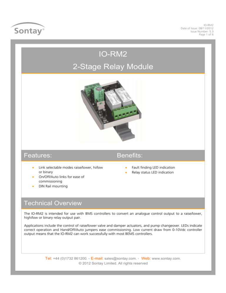
The IO-RM2 is intended for use with BMS controllers to convert an analogue control output to a raise/lower,
high/low or binary relay output pair.
Applications include the control of raise/lower valve and damper actuators, and pump changeover. LEDs indicate
correct operation and Hand/Off/Auto jumpers ease commissioning. Low current draw from 0-10Vdc controller
output means that the IO-RM2 can work successfully with most BEMS controllers.
Tel: +44 (0)1732 861200. - E-mail: sales@sontay.com. - Web: www.sontay.com.
© 2012 Sontay Limited. All rights reserved
IO-RM2
Date of Issue: 08/11/2012
Issue Number: 5.3
Page 2 of 6
Specification:
Input signal
Output contacts
Power supply:
Hysteresis
Operating modes:
Part Codes:
0-10Vdc 1mA min. into 22kΩ
impedance
8A at 230Vac (resistive load)
IO-RM2
2-Stage relay module
24Vac ±15% @ 50Hz or
24Vdc +15% -6%, 65mA max.
±0.2Vdc about switching points
Hi/Lo
1 raise/lower pair
Binary
LED indication:
Manual override
Electrical terminals
Ambient range:
Temperature
RH
Dimensions (H x W x H)
Country of origin
Supply OK
Supply voltage low
Supply voltage high
Relay Status
Hi input voltage
Incorrect input mode jumper
selection
Low input voltage (only in 210Vdc mode)
On/Off/Auto jumper selectable
Rising cage connectors for
0.5-2.5mm² cables
-10 to +40°C (14 to 107°F)
0-80% non-condensing
72 x 49.5 x 55
(2.83 x 1.95 x 2.17”)
UK
The products referred to in this data sheet meet the
requirements of EU 2004/108/EC and 2006/95/EC
Warning!
When installed, the output relay contacts may carry
240Vac. Special care must be taken to isolate the switched
voltages prior to any work being undertaken.
Tel: +44 (0)1732 861200. - E-mail: sales@sontay.com. - Web: www.sontay.com.
© 2012 Sontay Limited. All rights reserved
IO-RM2
Date of Issue: 08/11/2012
Issue Number: 5.3
Page 3 of 6
Installation:
Antistatic precautions must be observed when handling these modules. The PCB contains circuitry that can be
damaged by static discharge.
1.
The IO-RM2 should only be installed by a competent, suitably trained technician, experienced in installation with
hazardous voltages. (>50Vac & <1000Vac or >75Vdc & 1500Vdc)
2.
Ensure that all power is disconnected before carrying out any work on the IO-RM2.
3.
Maximum cable is 2.5mm², care must be taken not to over tighten terminals.
4.
When mounting the IO-RM2 care should be taken not to stress the PCB when fitting to the DIN rail. If it is necessary
remove the module from the DIN rail, be sure to use a flat bladed screwdriver to release the DIN clips.
5.
The IO-RM2 is designed to operate from a 24Vac/dc supply (so that power can be drawn from a 24Vac transformer
used for other purposes if a 24Vdc supply is not available). In either case one side of the supply is common to the
signal ground from the BEMS controller.
6.
The relay outputs are single Pole Change Over (SPCO) so they can be wired as Normally Open (N/O) or Normally
Closed (N/C).
7.
The 0-10Vdc signal input requires a minimum of 1mA to operate.
LED Status:
Power supply
Normal:
The green LED indicates the supply power condition. If power supply is normal (between 22V and 40V ±0.2V hysteresis) the
green LED is ON continuously, showing that the IO-RM2 is powered correctly.
Low Supply Voltage:
If power supply falls below about 21.8V the green LED double flashes twice a second;
*-*-----*-*-----*-*-----*-*
The low power condition clears at about 22.0V. The relays behave as normal.
High Supply Voltage:
If the power supply is above 40V the green LED flashes 6 times a second;
*-*-*-*-*-*
All the relays are switched off (except when forced ON by jumper settings) as excessive voltage might overload the voltage
regulator.
Tel: +44 (0)1732 861200. - E-mail: sales@sontay.com. - Web: www.sontay.com.
© 2012 Sontay Limited. All rights reserved
IO-RM2
Date of Issue: 08/11/2012
Issue Number: 5.3
Page 4 of 6
LED Status (continued):
The relays are switched off:
For 2 seconds after power-up
When the supply is greater than 40V
For 2 seconds after any over 40V condition clears
This prevents the relays from switching on and off during power-up or power failure with an over voltage power supply.
Control Input Voltage
The red LED indicates input voltage condition, normally the red LED is off
High Input:
If the input voltage exceeds 11V, ±0.2V hysteresis, the red LED goes on continuously. The relays behave as if 10Vdc were
applied. The input voltage should settle on one ‘voltage band’. Voltage is deemed to have settled after it has been within one
band for 250ms. If it has not settled for 500ms it is deemed to be unstable. If it is unstable the red LED flashes 6 times a
second:
*-*-*-*-*-*
The relay outputs remain at their last settled value.
Mode Select Error:
If the mode select jumper is missing or there is an inconsistent setting (such as connecting 2 jumpers) then this is an error.
The red LED does triple flashes:
*-*-*---*-*-*---*-*-*---*-*-*
The relays are switched off.
Low Input:
If the input voltage goes below 1.5Vdc, ±0.2Vdc hysteresis, when 2Vdc to 10Vdc input mode is selected then the red LED
does double flashes:
*-*-----*-*-----*-*-----*-*
Input Mode:
2Vdc to 10Vdc input mode:
This works the same as the normal 0-10Vdc input mode except that the input voltages are taken from 20% to 100% of the
full range, and are consequently more closely spaced. The bottom 20% is regarded as an error (see LED indications), and will
cause all relays to be off (unless jumpers force them on). Hysteresis around changeover voltages are 80% of the normal
0.2Vdc = 0.16Vdc.
Tel: +44 (0)1732 861200. - E-mail: sales@sontay.com. - Web: www.sontay.com.
© 2012 Sontay Limited. All rights reserved
IO-RM2
Date of Issue: 08/11/2012
Issue Number: 5.3
Page 5 of 6
Connections:
Green LED
Red LED
Override link’s
Input signal
Function link
Outputs;
Relay
NC
Normally open
NO
Normally closed
C
Common
AUT
ON
2-10
AUT
0-10
OFF
24V 0V 0V IP
ON
24Vac/dc
0V
0V
0(2) to 10Vdc
OFF
Inputs;
24V
0V
0V
IP
Relay LED’s
BIN
R/L
H/L
NC NO C
NC NO C
It is important not to mix SELV (safety extra low voltage) and non-SELV loads on the same IO-RM module. Consult BS 7671
for full details of SELV and non-SELV
Jumper Settings:
Function:
Input signal:
Binary
Override:
0-10Vdc
On
Off
Raise/Lower
2-10Vdc
Auto
High/Low
Tel: +44 (0)1732 861200. - E-mail: sales@sontay.com. - Web: www.sontay.com.
© 2012 Sontay Limited. All rights reserved
IO-RM2
Date of Issue: 08/11/2012
Issue Number: 5.3
Page 6 of 6
Switching Sequences:
Binary:
In
Input Voltage
0Vdc - 3Vdc
3Vdc - 5.5Vdc
5.5Vdc - 8Vdc
8Vdc - 10Vdc
Nominal
0Vdc
4Vdc
7Vdc
10Vdc
Relay 1
OFF
ON
OFF
ON
Relay 2
OFF
OFF
ON
ON
Raise/Lower:
Input Voltage
0Vdc - 3Vdc
3Vdc - 5.5Vdc
5.5Vdc - 8Vdc
8Vdc - 10Vdc
Nominal
0Vdc
4Vdc
7Vdc
10Vdc
Relay 1
OFF
ON
OFF
OFF
Relay 2
OFF
OFF
OFF
ON
High/Low:
Input Voltage
0Vdc - 3Vdc
3Vdc - 7.5Vdc
7.5Vdc - 10Vdc
Nominal
0Vdc
5Vdc
10Vdc
Relay 1
OFF
ON
ON
Relay 2
OFF
OFF
ON
Tech Tip:
Electrical Noise
By far the most common cause of electrical noise on a typical HVAC site is the contactor. Little, if any, electrical noise is
produced when the contactor coil is energized, but significant noise is produced when the coil de-energizes, and may exceed
700Vac P-P. Typically, the contactor coil is switched by the C & N/O contacts of an IO-RM module relay.
Fitting an “RF snubber” across the contactor coil is a good way of greatly reducing the electrical noise pulse produced when
the coil de-energizes. The ROXBURGH flying lead RC network type XEB1201 (Farnell part code 1187659) is a tried and
trusted component for this purpose. Alternatively, a suitable MOV (metal oxide varistor) across the IO-RM C & N/O relay
contacts will also help to prevent electrical noise being induced.”
Whilst every effort has been made to ensure the accuracy of this specification, Sontay cannot accept responsibility for damage, injury,
loss or expense from errors or omissions. In the interest of technical improvement, this specification may be altered without notice.
Tel: +44 (0)1732 861200. - E-mail: sales@sontay.com. - Web: www.sontay.com.
© 2012 Sontay Limited. All rights reserved

