AP Physics – Interference
advertisement
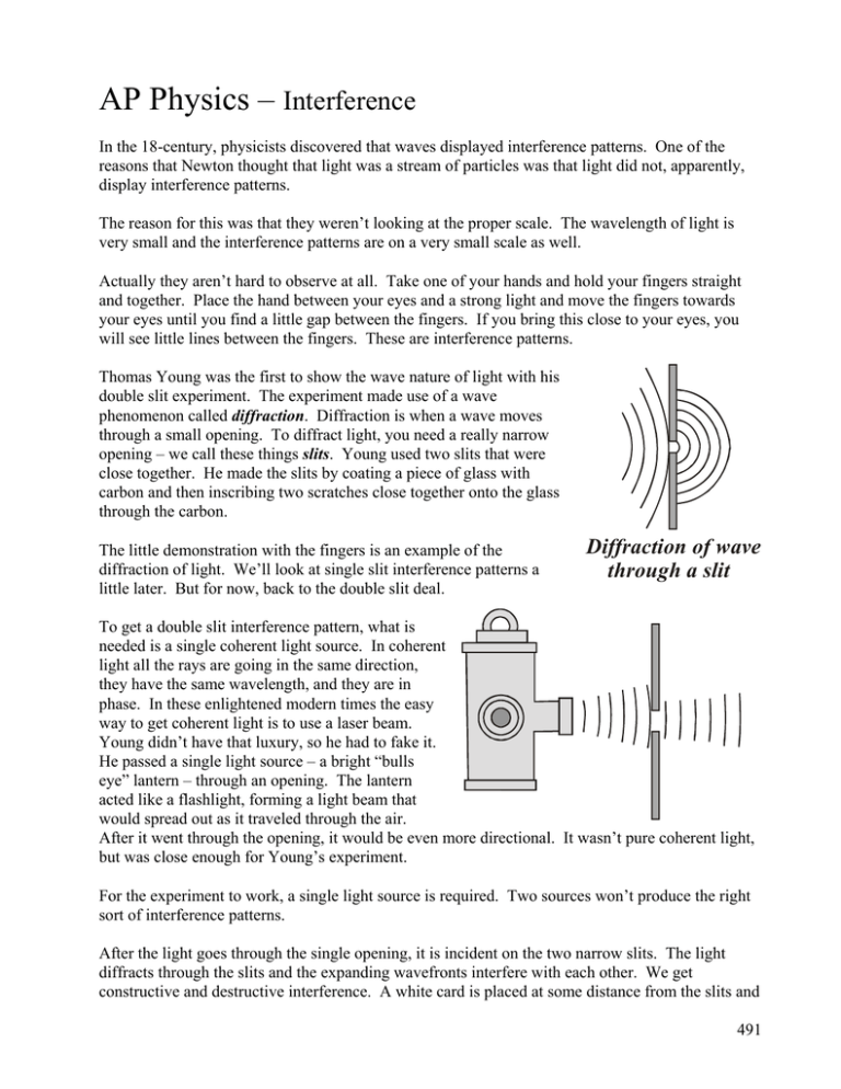
AP Physics – Interference In the 18-century, physicists discovered that waves displayed interference patterns. One of the reasons that Newton thought that light was a stream of particles was that light did not, apparently, display interference patterns. The reason for this was that they weren’t looking at the proper scale. The wavelength of light is very small and the interference patterns are on a very small scale as well. Actually they aren’t hard to observe at all. Take one of your hands and hold your fingers straight and together. Place the hand between your eyes and a strong light and move the fingers towards your eyes until you find a little gap between the fingers. If you bring this close to your eyes, you will see little lines between the fingers. These are interference patterns. Thomas Young was the first to show the wave nature of light with his double slit experiment. The experiment made use of a wave phenomenon called diffraction. Diffraction is when a wave moves through a small opening. To diffract light, you need a really narrow opening – we call these things slits. Young used two slits that were close together. He made the slits by coating a piece of glass with carbon and then inscribing two scratches close together onto the glass through the carbon. The little demonstration with the fingers is an example of the diffraction of light. We’ll look at single slit interference patterns a little later. But for now, back to the double slit deal. Diffraction of wave through a slit To get a double slit interference pattern, what is needed is a single coherent light source. In coherent light all the rays are going in the same direction, they have the same wavelength, and they are in phase. In these enlightened modern times the easy way to get coherent light is to use a laser beam. Young didn’t have that luxury, so he had to fake it. He passed a single light source – a bright “bulls eye” lantern – through an opening. The lantern acted like a flashlight, forming a light beam that would spread out as it traveled through the air. After it went through the opening, it would be even more directional. It wasn’t pure coherent light, but was close enough for Young’s experiment. For the experiment to work, a single light source is required. Two sources won’t produce the right sort of interference patterns. After the light goes through the single opening, it is incident on the two narrow slits. The light diffracts through the slits and the expanding wavefronts interfere with each other. We get constructive and destructive interference. A white card is placed at some distance from the slits and 491 the interference patters can be seen on the card. Where constructive interference has taken place we see a bright line. A dark line indicates destructive interference (no light energy). These lines, both the bright and dark ones, are called fringes. Let’s look at the wave diffracting through one of the slits and then both of the slits: Diffraction through one slit Diffraction through both slits Constructive interference takes place where the wave crests intersect. Destructive interference takes place sort of in between. If you place a card in the interference pattern, you can see the fringes. Max The destructive fringes are called minima and the constructive fringes are called maxima. This is basically what the thing looks like: The radial lines simply mark the intersection of the wave crests where the constructive interference is taking place. Reason for Interference Patterns: The basic reason that the interference patterns show up on the screen is that the light rays from each slit travel a different distance. Because of this, when they finally arrive at the screen they may or may not be in phase. If the waves arrive in phase from each slit, we get constructive interference and a maxima (bright fringe) appears on the screen. If they arrive out of phase, destructive interference takes place and we get a minima (dark fringe). Min Max Min Max Min Max Min Max Min Max Min Max Min Max Min Max 492 You can see this in the drawing below. At point P on the screen the waves arrive in phase and we get a bright fringe. Below P we see destructive interference in the drawing to the right. p p These drawings are very inaccurate, however – the Bright area scale is way off. Major, Dark area big-time off to be exact. Anyway, the wavelength is so small, the slits are really tiny, and the distance to the screen is enormous when compared with the wavelength and the slit width. The rays are actually almost parallel to each other when they reach the screen and are not separated by a big angle like the picture shows. The arrival of the waves at the screen looks more like this: In phase Out of phase The critical thing for the waves coming through the slits and meeting at the screen is this: in phase or out of phase? If they traveled the same distance, they would have to be in phase, but they don’t. They travel a different distance. So if we look at the path difference between the rays coming out of the slits we can figure this thing out. Is the path difference enough to make everything be in phase or out of phase? Path difference In phase Path difference Out of phase 493 If the path difference is zero or an integer multiple of the wavelength, we would get constructive interference. This would mean that the path difference could be the wavelength . Or the path difference could be 2 , 3 , 4 , 5 , &tc. If the waves arrive out of phase we get destructive interference. This would happen if the path difference is 1 3 5 7 or or or , etc. Here we would have an odd integer multiple of half 2 2 2 2 the wavelength. Do you see why this is so? Stop and think about it until you do. Here is a really fancy drawing showing the geometry of the path lengths. We have two slits, S1 and S2. Two rays are shown - the straight lines that go from the slits to the point P. P r1 y S1 d Q S2 q r2 q d sin q O L P is the point on the screen where the two waves arrive. d is the spacing between the slits. Q is the midpoint between the two slits and O is the point on the screen straight across from the slits. The angle is the angle between a line that connects Q to P. The path difference for light rays traveling through the slits is r2 r1 . Using a bit of geometry, you can see that a line dropped from the center of the first slit drawn perpendicular to the ray from the center of the second slit ( r2 ) makes a right triangle. This line has the angle . One side of the right triangle is d (the hypotenuse). The opposite side to the angle is d sin . This is a very key thing. The symbol for the path difference is . So the path difference is: r2 r1 d sin Clearly then, if the path difference is an integer multiple of the wavelength, we will get constructive interference. 494 d sin m where m 0, 1, 2, 3, &tc Thus: d sin m m fringe number 3 2 1 This is the equation you will have available on the AP Physics Test. Use it wisely. You end up with a central bright fringe. This is the zeroth-order maximum (m = 0). You can see that the angle would be zero for this fringe. The bright central fringe is bracketed by a series of smaller bright fringes for the different integer values of m. q q The next set of fringes is the first-order maximum, then we have the second-order maximum, and so on. 0 1 2 3 Because the slits are so small, the wavelength is really incredibly tiny, and the distance to the screen is humungous, the rays forming a fringe are essentially parallel and the angle is the same. Like this ridiculous drawing: r1 r2 S1 q S2 q d Example Problem: 495 A double slit setup has a slit spacing of 1.50 mm. A screen is set up 3.50 m from the double slit. Monochromatic light of wavelength 565 nm is incident on the slits. So find the angle for the first order bright fringe. d sin m m 1 sin d 565 x 109 m 1.50 x 10³ m 376.7 x 10⁶ 0.0003767 0.0216o Destructive Interference: Destructive interference will take place if the path difference is half of the wavelength or an odd multiple of half the wavelength. This way the waves will arrive 180 out of phase and we will get a minima. The equation for constructive interference is: d sin m So for the first order dark fringe, the first minima where m is 1 we get: d sin 1 2 For the second minima we would get d sin 3 2 And so on. Finding the Spacing Between Fringes: How do we calculate the spacing between the bright fringes? We start out with a drawing of the geometry of the double slit system. You can see it off to the right. We assume that L is much greater than d. The distance y is the spacing between the zeroith-order fringe and the first-order fringe. r1 y q d We also assume that d is much greater than . q r2 d sin q L The angle is very small, so small, that the sine of is essentially the same value as the tangent of . (This is only true for very small angles.) Therefore we can say: sin tan y L The reason we do this is that we can measure y and L. Look at the equation for the path difference: 496 d sin sin m We solve it for sin m d We plug in this value for sin in the path difference equation. sin ym m d y m L d L ym m d Solve the thing for y: L d Here ym is the spacing between the central fringe and the mth order fringe (does that make sense?). m is the integer, is the wavelength of the light, L is the distance from the slits to the screen, and d is the spacing between the two slits. Similarly: yDark L 1 m d 2 On the AP Physics Test the equation has a slightly different form: xm m L d You can see that it is the same thing as the one we developed, right? Red light ( = 664 nm) is used in Young’s experiment with slits separated by a distance of 1.20 x 10⁻⁴ m. The screen is located 2.75 m from the slits. Find the distance y on the screen between the central bright fringe and the third order bright fringe. xm m y 3 L d 664 x 109 m 2.75 m 4 1.20 x 10 m 4560 x 105 m 4.56 x 10² m or 4.56 cm A screen is separated from a double slit setup by a distance of 2.00 m. The slit spacing is 0.025 mm. Light passing through the slits has a second-order maximum that is 6.55 cm from the centerline. Find (a) the wavelength, (b) the distance between the adjacent fringes. 497 (a) The phrase “second-order maximum” means that m is 2. So there is a central bright fringe, a first order fringe, and a second order fringe. We have the spacing for the second order fringe from the center bright fringe. 103 m 5 2.5 x 102 mm 2.5 x 10 m 1 mm L dx xm m mL d 2.5 x 10 5 m 6.55 x 10² m 2 2.00 m 1 nm 4.09 x 10⁷ m 9 10 m 409 nm (b) Distance between fringes: What we must do is find the distance between the second order fringe and the first order fringe. This is the difference between the spacings of the fringes. y ym1 ym 4.09 x 10 x 7 m 1 m 2.00 m 2.5 x 10 5 m L d m L d m L d L d m L d L d 3.27 x 10² m or 3.27 cm Reflection & Phase: Light reflecting from a boundary can do so in phase (sort of a free end reflection) or out of phase (a fixed end reflection). The thing that determines whether the reflected wave is in or out of phase is the difference in speed for light in the two media. The wave will 180 phase change N o phase change n1 n 2 n1 n2 n1 n1 n 2 n2 undergo a 180 phase change when it is reflected from a medium that has a higher index of refraction than the one it came through. 498 There will be no phase change if the wave is reflected from a medium that has a lower refractive index. You would get the phase change for light traveling through air and reflecting off glass. Glass has a higher index of refraction than air. You would not get a phase change for light traveling through glass and being reflected off water, since water has a lower index of refraction than glass. This lead us to: Thin Film Interference: This occurs when light travels through a very thin layer of transparent material. Thin film interference occurs with oil films, soap bubbles, etc. Light that is incident on the film has several things happen to it. Some of the light is reflected off the top of the film. These waves have a 180 phase change since the index of refraction for the film is greater than for air. Next, the light that goes into the 180 phase No phase film is refracted as it travels from air into the film. Some change of the light goes into the air on the other side of the film. change This light is refracted (back the other way). Finally, some of the light is reflected off the air/film surface. This light does not undergo any phase change. 1 We have a lovely drawing showing how all this works. (See drawing to the right.) 2 Air The film has a thickness of t. We let n be the index of refraction for the film. The index of refraction for air is, of course, 1. Ray 1 reflecting off the surface of the film has a 180 phase change. Film t Air Ray 2 reflecting off the opposite film surface has no phase change. The two rays are out of phase. The two waves will recombine when you look into the film and the rays enter your eyes. If the path difference is half of the wavelength, or an odd multiple of the wavelength, then the waves will end up in phase and you will see constructive interference – a bright fringe. The basic kind of problem involves finding the minimum thickness that will cause constructive or destructive interference. This minimum would be when the wave came straight down onto the film. This means that the angle of incidence is zero. The surface reflected wave undergoes a 180 phase change. The wave that reflects off the bottom surface does not undergo a phase change. In order to get the bottom reflected wave to match up 499 with the first one, the path difference must be different by a half wavelength. The totals distance that the wave travels is twice the thickness of the film, 2 t. This must equal half a wavelength. Now the wavelength we’re talking about here is the wavelength of the light in the film. This is different than the wavelength in air (or the first medium if it ain’t air). So we have to carefully specify which wavelength we’re talking about. We’ll call the wavelength in the film f. This means that the minimum thickness is given by: 1 2t f 2 Unfortunately, we’re usually given the wavelength of the light in a vacuum, which is the same as the wavelength in air for our purposes, right? But we aren’t given the wavelength of the light in the film. So what do we do? Oh, poor poor pitiful us, whatever will we do? Well, we can figure this out, can’t we? We can solve for the wavelength in the film! We start with the equation for the index of refraction. n c v We solve for the speed of light. c nv This is true for any medium. So: c nv for air c nf vf and for the film set them equal nv n f v f v f The speed of a wave is given by: We can plug this into our equation for v. nv n f v f n f n f f f n n f f The frequency is the same in each medium: f so the wavelength for the film is: n nf So we can plug that into the equation: 1 2t f 2 t 1 n 2t 2 n f 2t n 2n f n 4n f 500 Index of Refraction and Wavelength: We’ve developed a very useful relationship in solving our little problem: n n f f . n11 n22 In general, we see that: Sadly, you won’t be given this equation on the AP Physics Test. So be prepared to figure it out. Light with a wavelength of 555 nm is incident on a soap bubble. What is the minimum thickness for thin film interference to take place for this wavelength of light? The index of refraction for the bubble goop is 1.35. 2t The minimum thickness is f 2 The path difference has to be half the wavelength of the light in the film and, of course, the path difference is twice the thickness of the film. But we don’t know what the wavelength of the light is in the film – we can figure it out however. n11 n22 2 1 n 2t 1 1 2 n2 t n11 n2 n11 4n2 555 nm 4 1.35 103 nm Destructive Interference on Thin Film: Destructive interference will take place if the path difference is equal to a single wavelength or an integer multiple of the wavelength. To find the minimum thickness, we go through the same deal. The minimum path length is 2 t, and it must be an integer multiple. 2t m f m 1, 2, 3, ... For the case where m is 1, we get 2t f Find minimum film thickness for destructive interference in reflected light if a thin film (n = 1.35) is illuminated by light that has wavelength of 585 nm. The minimum thickness is 2t f 501 n11 n22 2t f 2 2t n11 n2 n11 n2 t n11 2n2 585 nm 2 1.35 217 nm 180 phase 180 phase change change Thin Coatings: If the thin film rests on a surface that has a different index of refraction than what is on the on the other side, it is a thin coating. Thin coatings are used on glass lenses. Another example of a thin coating would be an oil slick, where a thin layer of oil rests on the water surface. Air If the coating has a lower index of refraction than the surface it rests on, light rays will undergo a 180 phase change from the bottom surface of the film as well as the upper surface. This makes everything opposite to what we saw for a thin film. Film Glass If the surface the coating rests on has a smaller index of refraction than the coating, then it is the same as for a thin film and we don’t need to go anywhere else with the thing. So for your standard thin coating, both reflected waves have the same phase. The interference again will depend on the path difference. You can see that the minimum thickness for constructive interference will be given by: 2t f The minimum thickness for destructive interference is given by: 2t f 2 Find the minimum film thickness for constructive interference in reflected light for a coating (nf = 1.30 ) on glass (ng = 1.60) is illuminated by light that has wavelength of 555 nm. 2t n t Air 2n Film Glass 502 We know that n11 n f f t 2n f so 1 5.55 nm 1 n11 t 2 n nf 2 1.42 n11 nf 195 nm Non Reflective Coatings: Non reflective coatings are used on camera lenses to get rid of unwanted glare and light highlights. To get rid of the flares, we want destructive interference to take place. This gives us the least amount of reflection. 180 phase 180 phase change Both rays undergo a 180 phase change. change Air Net change in phase from reflection is zero. To get destructive interference: 2t Film 2 A camera lens needs coating that will minimize reflection. nf = 1.25. Figure wavelength of light at 545 nm. What thickness? 2t 2t 2 2 n11 n22 so 1 545 nm 1 n t 1 1 4 n2 4 1.25 f Glass n11 n2 109 nm 503
