Cut Sheet
advertisement

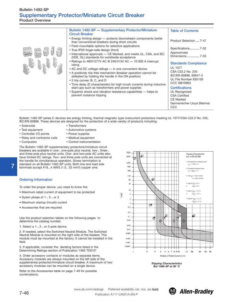
Bulletin 1492-SP Supplementary Protector/Miniature Circuit Breaker Product Overview Bulletin 1492-SP — Supplementary Protector/Miniature Circuit Breaker 0 Energy limiting design — protects downstream components better than conventional breakers during short circuits Field-mountable options for selective applications True IP2X finger-safe design (front) International approvals — CE Marked, and meets UL, CSA, and IEC (VDE, GL) standards for worldwide acceptance Ratings to 480Y/277V AC @ 240/415V AC — 10 000 A interrupt rating AC and DC voltage ratings — in one convenient device A positively trip-free mechanism (breaker operation cannot be defeated by holding the handle in the ON position) 3 trip curves: B, C, and D Time delay (D characteristic) for high inrush currents during inductive start-ups such as transformers and power supplies Superior shock and vibration resistance capabilities — helps to prevent nuisance tripping 1 2 3 4 5 6 7 Table of Contents Product Selection ...... 7-47 Specifications.............. 7-52 Approximate Dimensions................... 7-53 Standards Compliance UL 1077 CSA C22.2 No. 235 IEC/EN 60898, 60947-2 UL File Number E65138 CCC GB10963 Certifications UL Recognized CSA Certified CE Marked Germanischer Lloyd (Marine) CCC Bulletin 1492-SP series C devices are energy limiting, thermal magnetic type overcurrent protectors meeting UL 1077/CSA C22.2 No. 235, IEC/EN 60898. These devices are designed for the protection of a wide variety of products including: Solenoids Transformers Test equipment Automotive systems Controller I/O points Power supplies Relay and contractor coils Medical equipment Computers Control instrumentation The Bulletin 1492-SP supplementary protectors/miniature circuit breakers are available in one-, one-pole plus neutral, two-, three-, and three-pole plus neutral units. One- and two-pole AC units also have limited DC ratings. Two- and three pole units are connected at the handle for simultaneous operation. Screw termination is standard on all Bulletin 1492-SP units. Both line and load side terminals accept #18...4 AWG (1.0.. 25 mm2) copper wire. Tripping Characteristic acc. to EN 60.898 ➀ Conventional non-tripping current 1 = 1.13 Nt > 1 h nt ➁ Conventional tripping current 1 = 1.45IN:t < 1 h t ➂ 2.55 IN:t = 1-60 s (I<32 A) :t = 1-120 s (I<32 A) Ordering Information 8 ➃ Type B: 3IN:t > 0.1 s ➄ To order the proper device, you need to know the: t [sec] • Maximum rated current of equipment to be protected • Sytem phase of 1-, 2-, or 3 9 ➈ Type D: 10I :t = > 0. 1s N 20I :t = < 0. 1s N • Maximum startup (inrush) current • Accessories that are required 10 Use the product selection tables on the following pages to determine the catalog number. 1. Select a 1-, 2-, or 3-pole device. 11 2. If needed, select the Switched Neutral Module. The Switched Neutral Module is mounted on the right side of the breaker. This module must be mounted at the factory. It cannot be installed in the field. 3. If applicable, consider the derating factors listed in the Determining Ratings section of Publication 1492-TD010* 12 13 4. Order accessory contacts or modules as separate items. Accessory modules are always mounted on the left side of the supplemental protector/miniature circuit breaker. A maximum of two accessory modules can be mounted on a single device. Multiple of Rated Current (x ln) Tripping Characteristics Bul 1492-SP at 30 °C Refer to the Accessories table on page 7-49 for possible combinations. www.ab.com/catalogs 7-46 5IN:t < 0.1s ➅ Type C: 5I :t = > 0. 1s N ➆ 10I :t = < 0. 1s N Preferred availability cat. nos. are bold. Publication A117-CA001A-EN-P Bulletin 1492-SP Supplementary Protector/Miniature Circuit Breaker Product Selection Product Selection Trip Curve B Resistive or Slightly Inductive 1-Pole IEC 240/415V AC UL/CSA 277V AC 48V DC Trip Curve D Highly Inductive 10…20 In 3…5 In 5…10 In Continuous Current Rating (In) [A] Cat. No. Cat. No. Cat. No. 0.5 — 1492-SP1C005 1492-SP1D005 1 1492-SP1B010 1492-SP1C010 1492-SP1D010 2 1492-SP1B020 1492-SP1C020 1492-SP1D020 3 1492-SP1B030 1492-SP1C030 1492-SP1D030 4 1492-SP1B040 1492-SP1C040 1492-SP1D040 5 1492-SP1B050 1492-SP1C050 1492-SP1D050 6 1492-SP1B060 1492-SP1C060 1492-SP1D060 7 1492-SP1B070 1492-SP1C070 1492-SP1D070 8 1492-SP1B080 1492-SP1C080 1492-SP1D080 10 1492-SP1B100 1492-SP1C100 1492-SP1D100 13 1492-SP1B130 1492-SP1C130 1492-SP1D130 15 1492-SP1B150 1492-SP1C150 1492-SP1D150 16 1492-SP1B160 1492-SP1C160 1492-SP1D160 20 1492-SP1B200 1492-SP1C200 1492-SP1D200 25 1492-SP1B250 1492-SP1C250 1492-SP1D250 30 1492-SP1B300 1492-SP1C300 1492-SP1D300 32 1492-SP1B320 1492-SP1C320 1492-SP1D320 40 1492-SP1B400 1492-SP1C400 50 1492-SP1B500 1492-SP1C500 1 1492-SP1D500 63 1492-SP1B630 1492-SP1C630 1 1492-SP1D630 Tripping Characteristics Number of Poles Trip Curve C Inductive 1492-SP1D400 0 1 2 3 4 5 Note: Bulletin 1492-SP 1- and 3-pole circuit breakers are also available with neutral. Add a suffix of -N to the cat. no. 1 IEC only, does not have CCC, UR, or CSA certifications 6 7 8 9 10 11 12 13 www.ab.com/catalogs Preferred availability cat. nos. are bold. Publication A117-CA001A-EN-P 7-47 Bulletin 1492-SP Supplementary Protector/Miniature Circuit Breaker Specifications Specifications 1492-SP Series C 0 Description Tripping Characteristics 1 B Curve C Curve D Curve Resistive or Slightly-Inductive Loads Inductive Loads Highly-Inductive Loads Current Range 3…5 In 5…10 In 10…20 In 1…63 A 0.5…63 A 0.5…40 A Poles (18 mm width per pole) 1, 2, 3, 1 +N, 3 + N Dielectric Strength 1960V AC Shock 2 25 G Half Sine Wave for 11 ms (3 axes) Frequency Range: 10…2000 Hz Max. Amplitude (p-p) = 0.030 in. Max. Acceleration = 5 G 2 hours each of 3 axes Vibration Operating Temperature Range 3 23…104 °F (-5…+40 °C) non-condensing Shipment and Short-Term Temperature Limits -22…+158 °F (-30…+70 °C) Housing Material Nylon #18…8 AWG (1.0…10 mm2) Tightening Torque ⎯ 2.4 N•m (21 lb•in) Wire Size 4 #6…4 AWG (16…25 mm2) Tightening Torque ⎯ 3.1 N•m (27 lb•in) Recommended Wire Strip Length 0.51 in. (13 mm) 6000 operations (1 operation = 2 switching events) ON/OFF Electromechanical Life Switched Neutral Rating 277V AC 5 Supplementary Protector UL 1077 - Recognized Component QVNU2 - E65138 CSA C22.2 No. 235 Certified Component Certifications Use Group (UG) 6 UG A - General Industrial Terminals (FW) FW 3 Line and Load evaluated for field wiring Overload Rating (OL) OL 0 (general use) 1-Pole, 1-Pole + N Maximum Volts Tripping Current (TC) 7 8 277V AC 48V DC TC 1, 40 °C TC 1, 40 °C SC U2 SC U1 Short-Circuit Current Rating (SC) < 35 A 10 kA @ 277V AC; B and C Curve 5 kA @ 277V AC; D Curve 40, 50, 63 A 5 kA @ 277V AC; B, C, and D Curve 10 kA @ 48V DC; B, C, and D Curve 2-Pole, 3-Pole, 3-Pole + N Maximum Volts 480Y/277V AC 96V DC (2-pole - series) Tripping Current TC 2, 40 °C TC 2, 40 °C SC U2 SC U1 Short-Circuit Current Rating (SC) 9 < 35 A 10 kA @ 480Y/277V AC; B and C Curve 5 kA @ 480Y/277V AC; D Curve 40, 50, 63 A 5 kA @ 480Y/277V AC; B, C, and D Curve 10 kA @ 96V DC; B, C, and D Curve Miniature Circuit Breaker IEC/EN 60898 (VDE) IEC/EN 60947-2 (GL) (not including D50 and D63) CQC (GB-10963) (not including D50 and D63) Certifications 10 Rated Voltage Un 240/415VAC 48V DC (CE 60747-2) Rated Insulation Voltage Ui 440 VAC 4 kV (1.2/50) μsec Rated Impulse Withstand Voltage Uimp 11 Conventional Non-Tripping Current int = 1.13 ln Conventional Tripping Current it = 1/45 ln Reference Temperature 30 ºC Temperature Factor 0.5% /K Maximum Back-Up Fuse 12 125 A gL/gG Selectivity Class 3 Icn (IEC 60 898) = 10 kA Icu (IEC 60 947-2) = 15 kA Rated Short-Circuit Capacity Service Short-Circuit Capacity 13 Ics = 7.5 kA Climatic Conditions Acc to IEC 68-2 (25...55 ºC/ 90...95% RH) www.ab.com/catalogs 7-52 Preferred availability cat. nos. are bold. Publication A117-CA001A-EN-P Bulletin 1492-SP Supplementary Protector/Miniature Circuit Breaker Specifications/Approximate Dimensions Auxiliary Specifications Auxiliary Contact Module Dual Auxiliary Contact Module Auxiliary/Signal Alarm Module Cat. Nos. 1492-ASPH3, 1492ASPHH3, 1492-ASPHS3 0 Undervoltage Release Module Cat. Nos. 1492-ASPU115 1492-ASPU230 Degree of Protection IP20 (IP00) Dimensions See below Weight Mechanical Lifespan Minimum Impulse Duration Shunt Trip Module Cat. Nos. 1492-ASPA1 1492-ASPA2 0.045 kg 0.155 kg 0.155 kg 6000 operations 10 000 operations 4000 operations 2 — — > 15 ms — 1492-ASPU115: Un-115V AC, Umin-50V AC 1492-ASPA1: 110…415V AC, 110…230V AC — 1492-ASPU230: Un-230/240V AC, Umin-110V AC 1492-ASPA2: 12…110V AC, 12…60V AC Inrush Current — 3.6/44 mA (AC/DC) 25/12 mA (AC) 15/2 mA (DC) Dropout — 0.7…0.35 x Us — Voltage Range — — 0.7…1.1 x Us AC 13 @ 250V AC 3 A AC 15 @ 250V AC 0.5 A DC 12 @ 110V DC 0.5 A Umin-5V AC — — Terminal Capacity IEC Rigid, CU 0.5…2.5 mm2 2 x 0.5…2 x 2.5 mm2 0.5…4.0 mm2 2 x 0.5…2 x 2.5 mm2 1.0…25 mm2 2 x 1.0…2 x 4.0 mm2 Tightening Torque 0.8 N•m 1.1 N•m 2.4 N•m @ 230V AC 2 A @ 110V DC 0.5 A Umin-5V CDC — — #18…14 AWG 2 x #18…2 x #14 AWG #18…14 AWG 2 x #18…2 x #14 AWG #18…8 AWG 2 x 18…2 x #12 AWG 7 lb•in 10 lb•in 21 lb•in Operating Voltage Max. Operating Current EN/IEC Max. Operating Current UL 1077 CSA C22.2 No. 235 Terminal Capacity CU Tightening Torque 1 3 4 5 6 7 Approximate Dimensions Dimensions are shown in millimeters. Dimensions are not intended for manufacturing purposes. Bulletin 1492-SP Series C 8 9 10 Bulletin 1492-SP 11 12 Cat. No. 1492-ASPHH3 1492-ASPHS3 1492-ASPH3 Cat. No. 1492-ASPU_ _ _ Cat. No. 1492-ASPA_ 13 www.ab.com/catalogs Preferred availability cat. nos. are bold. Publication A117-CA001A-EN-P 7-53


