The Design on active balun employing InGaP/GaAs HBT
advertisement

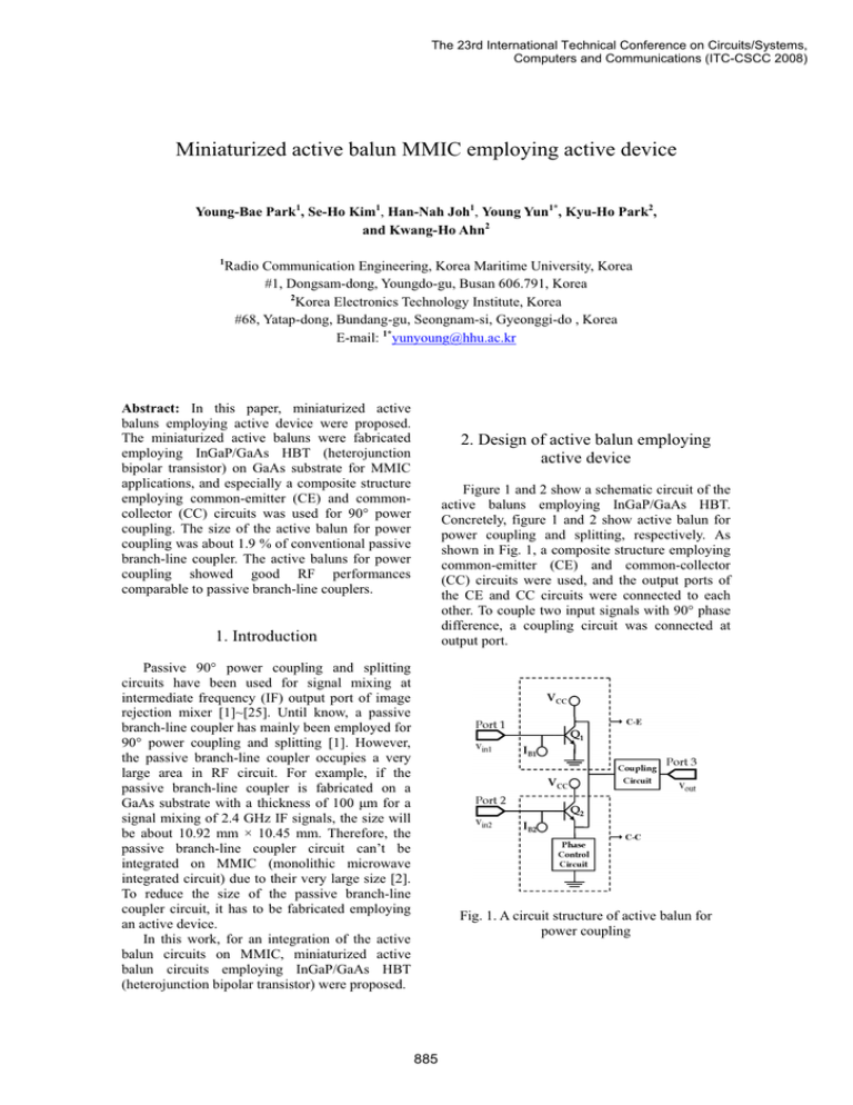
The 23rd International Technical Conference on Circuits/Systems, Computers and Communications (ITC-CSCC 2008) Miniaturized active balun MMIC employing active device Young-Bae Park1, Se-Ho Kim1, Han-Nah Joh1, Young Yun1*, Kyu-Ho Park2, and Kwang-Ho Ahn2 1 Radio Communication Engineering, Korea Maritime University, Korea #1, Dongsam-dong, Youngdo-gu, Busan 606.791, Korea 2 Korea Electronics Technology Institute, Korea #68, Yatap-dong, Bundang-gu, Seongnam-si, Gyeonggi-do , Korea E-mail: 1*yunyoung@hhu.ac.kr Abstract: In this paper, miniaturized active baluns employing active device were proposed. The miniaturized active baluns were fabricated employing InGaP/GaAs HBT (heterojunction bipolar transistor) on GaAs substrate for MMIC applications, and especially a composite structure employing common-emitter (CE) and commoncollector (CC) circuits was used for 90° power coupling. The size of the active balun for power coupling was about 1.9 % of conventional passive branch-line coupler. The active baluns for power coupling showed good RF performances comparable to passive branch-line couplers. 2. Design of active balun employing active device Figure 1 and 2 show a schematic circuit of the active baluns employing InGaP/GaAs HBT. Concretely, figure 1 and 2 show active balun for power coupling and splitting, respectively. As shown in Fig. 1, a composite structure employing common-emitter (CE) and common-collector (CC) circuits were used, and the output ports of the CE and CC circuits were connected to each other. To couple two input signals with 90° phase difference, a coupling circuit was connected at output port. 1. Introduction Passive 90° power coupling and splitting circuits have been used for signal mixing at intermediate frequency (IF) output port of image rejection mixer [1]~[25]. Until know, a passive branch-line coupler has mainly been employed for 90° power coupling and splitting [1]. However, the passive branch-line coupler occupies a very large area in RF circuit. For example, if the passive branch-line coupler is fabricated on a GaAs substrate with a thickness of 100 ȝm for a signal mixing of 2.4 GHz IF signals, the size will be about 10.92 mm × 10.45 mm. Therefore, the passive branch-line coupler circuit can’t be integrated on MMIC (monolithic microwave integrated circuit) due to their very large size [2]. To reduce the size of the passive branch-line coupler circuit, it has to be fabricated employing an active device. In this work, for an integration of the active balun circuits on MMIC, miniaturized active balun circuits employing InGaP/GaAs HBT (heterojunction bipolar transistor) were proposed. G G Fig. 1. A circuit structure of active balun for power coupling 885 GHz to 12.7 GHz. Fig. 2. A circuit structure of active balun for power splitting G Fig. 3. A photograph of the active balun employing InGaP/GaAs HBT for power coupling The coupling circuit was designed in order that the output gain (S31) of CE circuit is equal to output gain (S32) of CC circuit. The phase control circuit was properly designed for a 90° phase coupling of two input signals. 3. Measurement of active balun employing InGaP/GaAs HBT Figure 3 and 4 show the active baluns employing InGaP/GaAs HBT for power coupling and splitting, respectively, which were fabricated on GaAs MMIC. As shown in Fig. 3, the size of the fabricated active balun for power coupling is 2.05 mm u 1.05 mm, which is 1.9% of the size of a conventional passive branch-line coupler (if passive branch-line coupler with an operation frequency of 2.4 GHz is fabricated on GaAs MMIC, its size is 10.92 mm u 10.45 mm). As shown in Fig. 4, the size of the active balun for power splitting is 1.67 mm u 0.87 mm, which is 31.6% of a conventional passive branch-line coupler (if passive branch-line coupler with an operation frequency of 12 GHz is fabricated on GaAs MMIC, its size is 2.11 mm u 2.18 mm). Figure 5 shows a measured phase difference between S31 and S32 of active balun for power coupling. As shown in this figure, a phase difference characteristic of -90 ± 2.5q is observed from 2.3 GHz to 2.5GHz. The output gain characteristics (S31 and S32) of the active balun for power coupling was about 10 dB at 2.4 GHz. Concretely, the proposed active balun for power coupling showed a gain of 10 ± 1 dB from 2.3 GHz to 2.5 GHz. Figure 6 shows a measured phase difference between S21 and S31 of active balun for power splitting. As shown in this figure, a phase difference characteristic of -90 ± 3.0q is observed from 11.8 GHz to 12.1 GHz. An output gain (S21 and S31) of about 10 dB was observed at 12 GHz. Concretely, the proposed active balun for splitting shows a gain of 10 ± 1 dB from 11.5 Fig. 4. A photograph of the active balun employing InGaP/GaAs HBT for power splitting Fig. 5. Measured phase difference between S31 and S32 of active balun for power coupling Fig. 6. Measured phase difference between S21 and S31 of active balun for power splitting 886 InGaP/GaAs HBT (heterojunction bipolar transistor) on GaAs substrate for MMIC applications, and especially used a composite structure employing common-emitter (CE) and common-collector (CC) circuits for 90° power coupling. The size of the active balun for power coupling was about 1.9 % of conventional passive branch-line coupler. Form the active baluns, we could observe good RF performances comparable to passive branch-line couplers. Acknowledgment Fig. 7. Measured return loss characteristics of active balun for power coupling This work was supported by ETRI SoC Industry Promotion Center & Human Resource Development Project for IT SoC Architect. This work was also supported by KETI, Korea. References [1] S. A. Mass, Microwave mixer. Reading, MA: Artech House, 1986. [2] T. Sugiura, K. Honjo, and T. Tsuji, “12-GHzband GaAs dual-gate MESFET monolithic mixers,” IEEE Trans. Microwave Theory Tech., vol. MTT-33, pp. 105-110, Feb. 1985. [3] E. Camargo and W. Kennan, “An E-mode GaAs FET operating as a single balanced gate mixer,” IEEE Trans. MTT-S Int Microwave Symp. Dig., vol. 2, pp. 951-954, 1996. [4] K. Hubbard, K. MacGowan, C. Kau, D. Smith, and S. Mass, “A family of low cost high performance HEMT MMICs for commercial DBS application,” IEEE MTT-S Int. Microwave Symp. Dig., vol. 32, no. 5, pp. 340-344, Mar. 2002. [5] T. Kaneko, T. Miya, and S. Yoshida, “A Ku band converter IC,” IEEE MTT-S Int. Microwave Symp. Dig., vol. 1, pp. 451-454, Jun. 1992. [6] M. Chongcheawchamnan, GN. siripon, and I. D. Robertson, “Design and performance of improved lumped-distributed Wilkinson divider topplogy,” Electron. Lett., vol. 37, pp. 501-503, 2001. [7] A. S. Sedra, K. C. Smith, Microelectronic Circuits. MA: Oxford University Press, 2004. [8] S. Kudszus, M. Neumann, T. Berceli, and W. H. Haydl, “Fully integrated 94-GHz subharmonic injection-locked PLL circuit,” IEEE Microw.Wireless Compon. Lett., vol. 10, no. 2, pp. 70-72, Feb. 2000. [9] M. Sokolich, C. H. Fields, S. Thomas III, B. Shi, Y. K. Boegeman, M. Montes, R. Martinez, Fig. 8. Measured return loss characteristics of active balun for power splitting Table. 1. comparison of RF performances Circuit size Output gain/loss Phase difference Isolation Return loss Conventional branch-line coupler 10.92 × 10.45 mm -3.65 ¥ -3.61 dB Proposed active balun (Fig. 1) 2.05 × 1.05 mm +10.5 ¥ +10.3 dB -89.8° -92.6° -34.8 dB -38.5 dB -26.6 dB¥ -26.5 dB -10.7 dB ¥ -8.5 dB Figure 7 and 8 shows measured return loss characteristics of active balun for power coupling and splitting, respectively. RF performances of the active balun for power coupling was summarized in Table 1. 4. Conclusion In this paper, we propose miniaturized active baluns employing active device. We fabricated the miniaturized active baluns employing 887 A. R. Kramer, and M. Madhav, “A low-power 72.8-GHz static frequency divider in AlInAs/InGaAs HBT technology,” IEEE J. Solid-State Circuits, vol. 36, no. 9, pp. 1328– 1334, Sep. 2001. [10] H. Knapp, M. Wurzer, T. F. Meister, K. Aufinger, J. Bock, S. Boguth, and H. Schafer, "86 GHz static and 110 GHz dynamic frequency dividers in SiGe bipolar technology,” IEEE MTT-S Int. Microwave Symp. Dig., 2003, pp. 1067–1070. [11] Z. Lao, A. Thiede, J. Hornung, M. Schlechtweg, H. Lienhart, W. Bronner, A. Huelsmann, T. Jakobus, J. Seibel, M. Sedler, and G. Kaufel, “55-GHz dynamic frequency divider IC,” Electron. Lett., vol. 34, no. 20, pp. 1973–1974, Oct. 1998. [12] C. Rauscher, “Regenerative frequency division with a GaAs FET,” IEEE Trans. Microw. Theory Tech., vol. MTT-32, no. 11, pp. 1461–1468, Nov. 1984. [13] J. Sarkissian, M. Camiade, P. Savary, A. Suarez, R. Quere, and J. Obregon, “A 60-GHz HEMT–-MMIC analog frequency divider by two,” IEEE J. Solid-State Circuits, vol. 30, no. 10, pp. 1062–1067, Oct. 1995. [14] S. Kudszus, W. H. Haydl, M. Neumann, and M. Schlechtweg, “94/47-GHz regenerative frequency divider MMIC with low conversion loss,” IEEE J. Solid-State Circuits, vol. 35, no. 9, pp. 1312–1317, Sep. 2000. [15] K. Honjo and M. Madihian, “Novel design approach for X-band GaAs monolithic analog 1/4 frequency divider,” IEEE Trans. Microw. Theory Tech., vol. MTT-34, no. 4, pp. 436– 441, Apr. 1986. [17] J. Jeong and Y. Kwon, “V -band harmonic injection-locked frequency divider using cross-coupled FETs,” IEEE Microw.Wireless Compon. Lett., vol. 14, no. 10, pp. 457–459, Oct. 2004. [18] C. J. Madden, D. R. Snook, R. L. Van Tuyl, M. V. Le, and L. D. Nguyen, “A novel 75 GHz InP HEMT dynamic divider,” GaAs IC Symp. Dig., 1996, pp. 137–140. [19] T. Ohira and Y. Suzuki, “Novel frequency division technique for very low power GaAs monolithic microwave prescalers,” IEEE MTT-S Int. Microwave Symp. Dig., 1999, pp. 193–196. [20] H. R. Rategh and T. H. Lee, “Superharmonic injection-locked frequency dividers,” IEEE J. Solid-State Circuits, vol. 34, no. 6, pp. 813–821, Jun. 1999. [21] F. Ramirez, M. Elena de Cos, and A. Suarez, “Nonlinear analysis tools for the optimized design of harmonic-injection dividers,” IEEE 888 Trans. Microw. Theory Tech., vol. 51, no. 6, pp. 1752–1762, Jun. 2003. [22] R. Adler, “A study of locking phenomena in oscillators,” Proc. IEEE, vol. 61, no. 10, pp. 1380–1385, Oct. 1973. [23] J. Kim and Y. Kwon, “Intermodulation analysis of dual-gate FET mixers,” IEEE Trans. Microw. Theory Tech., vol. 50, no. 6, pp. 1544–1555, Jun. 2002. [24] K. Kanazawa,M. Hagio, M. Kazumura, and G. Kano, “A 15 GHz single stage GaAs dualgate FET monolithic analog frequency divider with reduced input threshold power,” IEEE Trans. Microw. Theory Tech., vol. 36, no. 12, pp. 1908–1912, Dec. 1988. [25] K. Kurokawa, “Injection locking of microwave solid-state oscillators,” Proc. IEEE, vol. 61, no. 10, pp. 1386–1410, Oct. 1973.


