06) EM Induction
advertisement

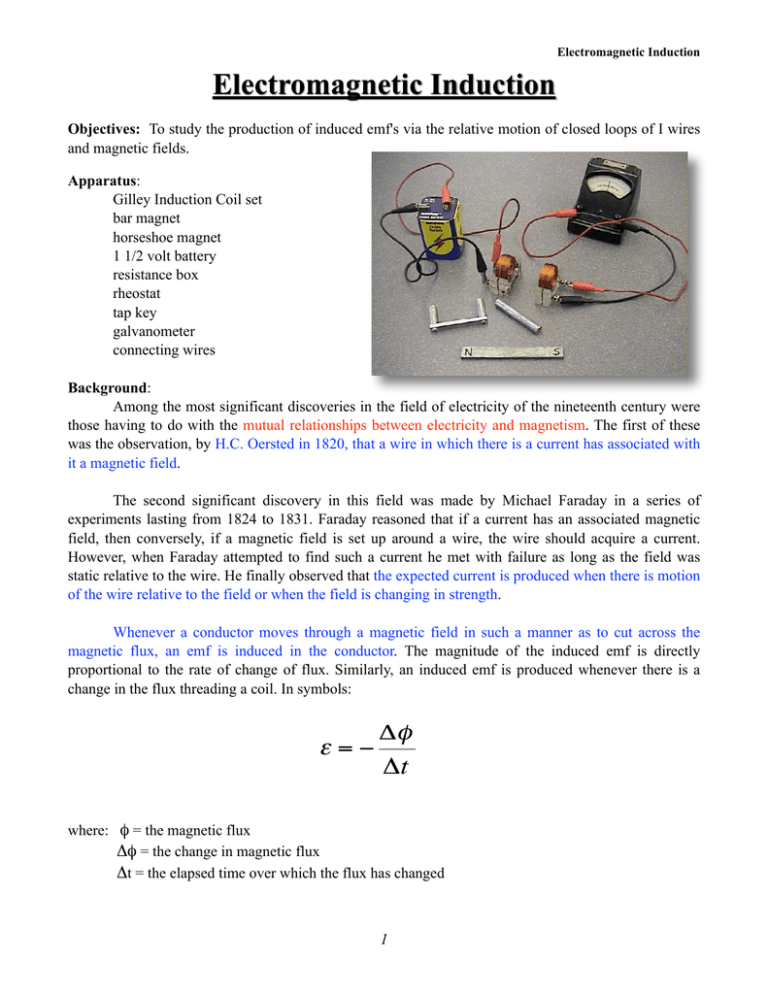
Electromagnetic Induction Electromagnetic Induction Objectives: To study the production of induced emf's via the relative motion of closed loops of I wires and magnetic fields. Apparatus: Gilley Induction Coil set bar magnet horseshoe magnet 1 1/2 volt battery resistance box rheostat tap key galvanometer connecting wires Background: Among the most significant discoveries in the field of electricity of the nineteenth century were those having to do with the mutual relationships between electricity and magnetism. The first of these was the observation, by H.C. Oersted in 1820, that a wire in which there is a current has associated with it a magnetic field. The second significant discovery in this field was made by Michael Faraday in a series of experiments lasting from 1824 to 1831. Faraday reasoned that if a current has an associated magnetic field, then conversely, if a magnetic field is set up around a wire, the wire should acquire a current. However, when Faraday attempted to find such a current he met with failure as long as the field was static relative to the wire. He finally observed that the expected current is produced when there is motion of the wire relative to the field or when the field is changing in strength. Whenever a conductor moves through a magnetic field in such a manner as to cut across the magnetic flux, an emf is induced in the conductor. The magnitude of the induced emf is directly proportional to the rate of change of flux. Similarly, an induced emf is produced whenever there is a change in the flux threading a coil. In symbols: ε=− Δφ Δt where: φ = the magnetic flux Δφ = the change in magnetic flux €time over which the flux has changed Δt = the elapsed 1 Electromagnetic Induction Note: The magnetic flux, φ , linking an area is the product of the area and the component of the magnetic intensity, B, perpendicular to the area. B A φ = ABcosθ θ € If the N pole of a magnet is moved toward a coil, Fig. 2a, an emf is induced in the coil and there is a current in the closed circuit in the direction indicated by the arrows. The field of the current is opposite in direction to that of the magnet and thus tends to oppose the increase of the field. When the N pole is moved away from the coil, Fig. 2b, the current reverses in direction. In this case, the field caused by the current is in the same direction as the field of the magnet and opposes the decrease in field. Lenz's law states the general condition for the direction of an induced emf, "Whenever there is an induced emf, it is in such a direction as to tend to oppose the change that caused it" This law is a form of the law of conservation of energy. 2 Electromagnetic Induction Procedure: 1. In order to determine the directions of the induced currents, it is first necessary to determine the direction of the galvanometer deflection corresponding to a known direction of current. Connect the galvanometer into a potential divider circuit, Fig. 3. Use a dry cell as a source and set the slider of the rheostat to tap off one or two wires of the slidewire. Note the direction of the current when the tap key is closed, and note the direction of deflection of the galvanometer. Arrange polarity of cell so that galvanometer deflects toward terminal marked positive on the meter. Use this information throughout the experiment to determine the direction of the induced current. 2. Loop of wire and Bar Magnet: Attach a long wire to the terminals of the galvanometer and make a single loop of wire. Thrust the N pole of the bar magnet quickly into the loop and note the deflection of the galvanometer. N Figure 4 S 3 Electromagnetic Induction a) What is the direction of the current through the loop? (This question, and all like it, is best answered with a drawing). b) Use the right-hand rule to find the direction of the field due to the induced current. Is the direction in accord with Lenz's Law? Repeat questions a and b when you i. Quickly pull the bar magnet out of the loop. ii. Thrust the S pole of the magnet through the loop. iii. Hold the bar magnet stationary and quickly thrust the loop over the N pole of the magnet, 3. Connect one of the coils to the galvanometer. Note the way the wire is wound on the coil. Record the direction of the current each time as clockwise or counter-clockwise a viewed from the side on which the binding posts are mounted. Thrust the N pole of the magnet toward the coil and note the deflection of the galvanometer. Explain deflection in terms of Lenz's law. Hold magnet stationary near the coil and note galvanometer reading. Explain. Withdraw the N pole and explain the result. Repeat, using the S pole. Figure 5: (for part 3) Figure 6: (for part 4) 4. Connect the second coil in series with a dry cell, and a tap key. Connect the cell so that the current in the coil is clockwise as viewed from the side opposite to the binding posts. Set this coil immediately adjacent to the coil connected to the galvanometer and with their axes in line. Close the switch and note the deflection. Is the induced current in the secondary coil in the same or opposite direction to that in the primary coil? Explain in terms of Lenz's law. With the key closed note the reading of the galvanometer. Explain. Open the switch and note the direction of the induced current. Is the induced current in the same or the opposite direction to that in the primary coil? Explain in term of Lenz's law. Repeat with the coils separated by a half inch. Explain the effect of the separation. 5. With the cells in the initial position of Step 4, close the switch of the primary circuit. After the pointer has come to rest, quickly move the primary coil away from the secondary. Note and explain 4 Electromagnetic Induction the deflection. Quickly replace the primary coil. Note and explain the deflection. Repeat these readings with the coil moved slowly. Explain the difference in the two effects. 6. Set the two coils in the position shown. Close the switch and note the deflection. Insert the soft-iron core and again close the switch and note the deflection. What does this indicate as to the effect of the presence of the iron core? Change the distance between the coils with the iron core still joining them. Close the switch and compare the reading with the one previously taken by use of the iron core. Does the distance between the coils materially affect the reading? Explain. Figure 7 7. Set the two coils in the position shown. Close the switch and note the deflection. Insert the U-shaped soft iron and again close the switch. Explain the difference. What does this experiment show regarding the path of the flux? Figure 8 8. Summarize the results of all these experiments. What factors are common to all the experiments? State the conclusions that you can reach concerning the factors upon which the value of the induced emf depends. 5


