PREMIUM SURGE PROTECTION
Diagnostic Test Set
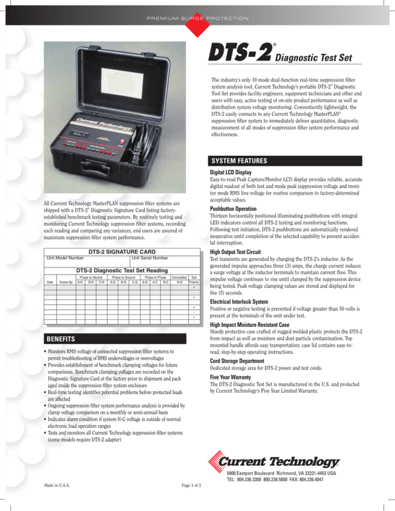
The industry’s only 10 mode dual-function real-time suppression filter
system analysis tool, Current Technology’s portable DTS-2® Diagnostic
Tool Set provides facility engineers, equipment technicians and other end
users with easy, active testing of on-site product performance as well as
distribution system voltage monitoring. Conventiently lightweight, the
DTS-2 easily connects to any Current Technology MasterPLAN®
suppression filter system to immediately deliver quantitative, diagnostic
measurement of all modes of suppression filter system performance and
effectiveness.
SYSTEM FEATURES
Digital LCD Display
All Current Technology MasterPLAN suppression filter systems are
shipped with a DTS-2® Diagnostic Signature Card listing factoryestablished benchmark testing parameters. By routinely testing and
monitoring Current Technology suppression filter systems, recording
each reading and comparing any variances, end users are assured of
maximum suppression filter system performance.
Unit Serial Number
DTS-2 Diagnostic Test Set Reading
Date
Tested By
Phase to Neutral
A-N
B-N
C-N
Phase to Ground
A-G
B-G
C-G
Pushbutton Operation
Thirteen horizontally positioned illuminating pushbuttons with integral
LED indicators control all DTS-2 testing and monitoring functions.
Following test initiation, DTS-2 pushbuttons are automatically rendered
inoperative until completion of the selected capability to prevent accidental interruption.
High Output Test Circuit
DTS-2 SIGNATURE CARD
Unit Model Number
Easy-to-read Peak Capture/Monitor LCD display provides reliable, accurate
digital readout of both test and mode peak suppression voltage and monitor mode RMS line voltage for routine comparison to factory-determined
acceptable values.
Phase to Phase
Uninstalled Test
A-B
A-C
B-C
N-G
Polarity
+
+
+
+
-
BENEFITS
• Monitors RMS voltage of connected suppression filter systems to
permit troubleshooting of RMS undervoltages or overvoltages
• Provides establishment of benchmark clamping voltages for future
comparisons. Benchmark clamping voltages are recorded on the
Diagnostic Signature Card at the factory prior to shipment and pack
aged inside the suppression filter system enclosure
• Real-time testing identifies potential problems before protected loads
are affected
• Ongoing suppression filter system performance analysis is provided by
clamp voltage comparison on a monthly or semi-annual basis
• Indicates alarm condition if system N-G voltage is outside of normal
electronic load operation ranges
• Tests and monitors all Current Technology suppression filter systems
(some models require DTS-2 adapter)
Test transients are generated by charging the DTS-2’s inductor. As the
generated impulse approaches three (3) amps, the charge current induces
a surge voltage at the inductor terminals to maintain current flow. This
impulse voltage continues to rise until clamped by the suppression device
being tested. Peak voltage clamping values are stored and displayed for
five (5) seconds.
Electrical Interlock System
Positive or negative testing is prevented if voltage greater than 50 volts is
present at the terminals of the unit under test.
High Impact Moisture Resistant Case
Sturdy protective case crafted of rugged molded plastic protects the DTS-2
from impact as well as moisture and dust particle contamination. Top
mounted handle affords easy transportation; case lid contains easy-toread, step-by-step operating instructions.
Cord Storage Department
Dedicated storage area for DTS-2 power and test cords.
Five Year Warranty
The DTS-2 Diagnostic Test Set is manufactured in the U.S. and protected
by Current Technology’s Five Year Limited Warranty.
®
5900 Eastport Boulevard Richmond, VA 23231-4453 USA
TEL: 804.236.3300 800.238.5000 FAX: 804.236.4047
Made in U.S.A.
Page 1 of 2
PREMIUM SURGE PROTECTION
Diagnostic Test Set
Testing vs. Monitoring: Gauging the Difference
Unlike their predecessors, today’s advanced electrical
transient protection devices actively test suppression
components. This ingenuity goes beyond the passive
monitoring included in yesterday’s offerings and allows
for quantitative measurement of suppression filter
system performance.
Wouldn’t a proactive approach be more sensible in
both scenarios? With a quick under-the-hood oil check
and glance at the dashboard guages, a driver can easily
assess the oil pressure and engine temperature and
thereby avoid potentially damaging situations. Why
not apply the same philosophy to suppression filter
systems?
Monitoring: After the Fact
The majority of electrical transient protection manufacturers offer continuous monitoring in the form of
visual indicators — such as lights or LED’s — that
assure the user of ongoing operation. All major vendors offer status indication of fuses or overcurrent protection in line with the device’s suppression elements.
The purpose of monitoring series overcurrent protection is to provide notification if the protection is
opened or tripped by a suppression component short
circuit. When a metal oxide varistor (MOV) or silicon
avalanche diode (SAD) fails, the failure is a momentary
short circuit condition. During this short circuit, properly coordinated overcurrent protection will open; systems with overcurrent protection monitoring will indicate that the overcurrent device has opened.
The “Idiot Light Syndrome”
Most electrical transient protection manufacturers
subscribe to one of two system monitoring approaches.
Some choose to individually fuse each MOV, yet monitor only one fuse in a multitude of MOVs. Others
include coordinated overcurrent protection for several
suppression components at once. Regardless of which
method is undertaken, monitoring has one undeniable
shortcoming: monitoring indicates a system failure
after the fact. The time for prevention is long past.
To date, the entire concept of electrical transient protection monitoring has been to reactively indicate that
a device has suffered a component failure — an attitude that has been labeled “the idiot light syndrome.”
When the oil or temperature light becomes illuminated on the dashboard of a car with “idiot lights” instead
of gauges, There’s a good chance that preventable damage has already been done.
Passing the Test
When today’s suppression filter systems user performs
routine maintenance for other distribution system
equipment, he or she should have the ability to“check
the oil and assess the gauges” on the facility’s suppression filter system, not only to verify system function,
but to determine the level of system performance.
Since 1992, all Current Technology suppression filter
systems have included a diagnostic test point comprised of a multi-pin connector wired directly into the
suppression and filtering components. Using the
accompanying DTS-2 Diagnostic Test Set, today’s facility engineer or factory-trained Current Technology
representative can actually perform field transient testing to verify function and performance levels of
Current Technology products. Current Technology’s
DTS-2 offers testing and monitoring beyond the “idiot
light syndrome.”
Monitoring is practical but passive. Proactive testing is
safe, simple and smart. Devices offering both provide
consumers with increased confidence.
Waiting for that bad utility day, that big thunderstorm,
that last motor switching or last big impulse to illuminate visual indicators could be a costly catastrophe.
Wouldn’t driving a car with gauges instead of idiot
lights give you greater peace of mind? That same security is available only with Current Technology suppression filter systems and the DTS-2 Diagnostic Test Set.
®
5900 Eastport Boulevard Richmond, VA 23231-4453 USA
TEL: 804.236.3300 800.238.5000 FAX: 804.236.4047
Page 2 of 2
© 2007 Current Technology®, DTS-2® and MasterMIND® Printed in U.S.A.
2M/7.12.07 /DTS-2
PREMIUM SURGE PROTECTION
Standard Warranty
Current Technology warrants that your Current
Technology surge protective device (the "Product"),
shall meet applicable industry standards and specifications and be free from defects in materials and/or workmanship. Should any failure of the Product to conform
to this warranty appear within the standard warranty
period, Current Technology shall either repair or
replace the defective Product, or part thereof, upon
return to Current Technology manufacturing facility in
Richmond, Virginia with transportation charges prepaid. The applicable warranty period is outlined below in
the warranty period section.
MasterPlan® Extended Warranty
The warranty period is extended to twenty (20) years if
the Product meets all of the following criteria:
a) The product is purchased simultaneously with a
Select 2 selenium-enhanced SL2-300, SL2-250 or
SL2-200 suppression filter system and
b) the product is installed simultaneously with a
Select 2 selenium-enhanced SL2-300, SL2-250 or
SL2-200 suppression filter system and
c) the product is installed electrically downstream
from a Select 2 selenium-enhanced SL2-300,
SL2-250 or SL2-200 suppression filter system.
Current Technology shall have no liability under this
warranty for any problems or defects directly or indirectly caused by misuse of the Product, alteration of the
Product (including removal of any warning labels), accidents, or improper installation, application, operation,
or repair of the Product.
The liability of Current Technology under this warranty is
expressly limited to the replacement or repair of the defective
part thereof, at Current Technology sole option.
IN NO EVENT SHALL CURRENT TECHNOLOGY BE LIABLE
FOR SPECIAL, INCIDENTAL, OR CONSEQUENTIAL DAMAGES OF ANY KIND OR CHARACTER, NOR SHALL
CURRENT TECHNOLOGY’ LIABILTY EVER EXCEED THE
PURCHASE PRICE PAID FOR SUCH DEFECTIVE PRODUCT.
This warranty is not transferable and may only be enforced by
the sole purchaser. Claims under this warranty must be submitted to Current Technology within thirty (30) days of discovery of any Current Technology product defect.
WARRANTY PERIOD
Select2
Select Compact
HPI
TransGuard
CurrentGuard Plus
CurrentGuard
CurrentGuard Compact
Electronic Grade Panelboards
EGPE2
TransEnd
LoadGuard
Monitoring & Diagnostic Tools
Standard
20 Years
15 Years
20 Years
15 Years
15 Years
10 Years
10 Years
10 Years
5 Years
5 Years
5 Years
MasterPlan®
—
20 Years
20 Years
20 Years
20 Years
20 Years
20 Years
20 Years
20 Years
20 Years
20 Years
®
5900 EASTPORT BLVD.
RICHMOND, VA 23231-4453
TEL.: 804.236.3300 / 800.238.5000
FAX: 804.236.4047
www.currenttechnology.com
©2009 Current Technology All Rights Reserved Printed in U.S.A.
500M/4.7.09 750-0072-006


