ISSN: 2278 – 909X
International Journal of Advanced Research in Electronics and Communication Engineering (IJARECE)
Volume 5, Issue 8, August 2016
Design Of Wide Band Microstrip Power Divider
Using Advance Design System
K.KARTHIKA, C.KOHILA
Abstract— The design of micro-strip power divider is
constructed by dividing Quarter wavelength transmission line
into two. The simulation platform which we are going to use is
Advanced Design System (ADS). Complex isolation component
provides physical separation and electrical isolation between
two output ports. In the proposed method, good impedance
matching at all the three ports and perfect isolation between
two output ports are obtained over the specified 2-12 GHz WB
range coupled line section. It can also be used as power
combiner when used in reverse. This microstrip circuit with
FR-4 substrate with suitable length, width, permittivity is
analysed using ADS software. Here the power dividers are
implemented in microstrip transmission medium. The
proposed model of power divider operates in wide bandwidth
with good isolation factor. Finally, the performance of equal
split power dividers are examined and the simulated results
are compared with measured results.
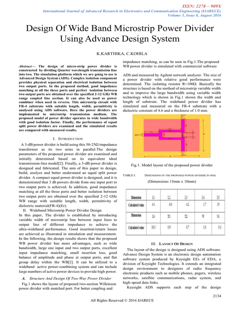
impedance matching, as can be seen in Fig.1.The proposed
WB power divider is simulated with commercial software
ADS and measured by Agilent network analyzer. The size of
a power divider with relative good performance were
determined. The isolating resistor R=100Ω. Basically the
structure is based on the method of microstrip variable width
and to improve the large bandwidth using variable width
technology which is shown in Fig.1 shown the width and
length of substrate. The wideband power divider has
simulated and measured on the FR-4 substrate with a
dielectric constant of 4.6 and a thickness of 1.0 mm.
I. INTRODUCTION
A 3-dB power divider is build using this 50-25Ω impedance
transformer as its two arms in parallel.The design
parameters of the proposed power divider are examined and
initially determined based on its equivalent ideal
transmission-line model[2]. Finally, a 3-dB power divider is
designed and fabricated. The aim of this paper to design,
build, analyze and better understand an equal split power
divider. A compact equal power divider is designed, and it is
demonstrated that 3 db powers divide from one input port to
two output ports is achieved. In addition, good impedance
matching at all the three ports and better isolation between
two output ports are obtained over the specified 2-12 GHz
WB range with suitable length, width, permittivity of
dielectric material(FR-4)(Er).
II. Wideband Microstrip Power Divider Design
In this paper, The divider is established by introducing
variable width of microstrip line between input lines to
output line of different impedance to achieve the
ultra-wideband performance. Good insertion/return losses
are achieved as illustrated in simulation and measurement.
In the following, the design results shows that the proposed
WB power divider has more advantages, such as wide
bandwidth, large one input and two output ports, excellent
input impedance matching, small insertion loss, good
balance of amplitude and phase at output ports, and flat
group delay within the WB[2]. It can be utilized to a
wideband active power-combining system and can include
large numbers of active power devices to provide high power.
A. Structure And Design Of Two-Way Power Divider
Fig.1 shows the layout of proposed two-section Wilkinson
power divider with matched port. For better coupling and
Fig.1. Model layout of the proposed power divider
TABLE I.
DIMENSIONS OF THE PROPOSED POWER DIVIDER( IN MM)
(Dimensions 15mm x 10mm)
III. LAYOUT OF DESIGN
The layout of the design is designed using ADS software.
Advance Design System is an electronic design automation
software system produced by Keysight EEs of EDA, a
division of Keysight Technologies. It extends an integrated
design environment to designers of radio frequency
electronic products such as mobile phones, pagers, wireless
networks, satellite communications, radar system, and
high-speed data links.
Keysight ADS supports each step of the design
2134
All Rights Reserved © 2016 IJARECE
ISSN: 2278 – 909X
International Journal of Advanced Research in Electronics and Communication Engineering (IJARECE)
Volume 5, Issue 8, August 2016
process-schematic capture, layout, design rule checking,
frequency and time-domain circuit simulation, and
electromagnetic field simulation-allowing the engineer to
fully characterize and optimize an radio frequency design
without changing tools.
Fig 5. Measured result of return loss
Fig 5. Measured result of return loss
Fig 2. Layout of equal power divider
Fig 3. 3 D view of equal power divider
IV.
RESULT
The simulated result of return loss for equal power
divider is about -15.669dB at the frequency of 5.570 GHz is
shown in the fig.4.
Fig 4. Simulated result
Return loss is a scalar measure of how near the actual
input impedance of the network is to the nominal system
impedance value and, expressed in logarithmic magnitude.
Fig 6. Simulated result of Insertion losses
Fig.6 shows the simulated insertion loss is -3.723dB at
2.440GHz.
Fig 7. Simulated Isolation Results
Fig.7 shows the simulated isolation value is -54.301 at
7.860GHz.
2135
All Rights Reserved © 2016 IJARECE
ISSN: 2278 – 909X
International Journal of Advanced Research in Electronics and Communication Engineering (IJARECE)
Volume 5, Issue 8, August 2016
[7]. K. Song, Y. Fan, and Z. He, “Broadband radial waveguide spatial
combiner,” IEEE Microw. Wireless Compon. Lett., vol. 18, no. 2, pp 73–75,
Feb. 2008.
[8]. K. Song and Q. Xue, “Planar probe coaxial-waveguide power combiner/
divider,” IEEE Trans. Microw. Theory Tech., vol. 57, no. 11,pp. 2761–2767,
Nov. 2009.
[9]. Y. Koike, S. Ishii, and R. Kohno, “DS/chirp hybrid industrial WB for
ranging and high reliability communications,” in Proc.14th APCC, 2008,pp.
1–5.
[10]. C. I. G., Hsu, L. Ching-Her, et al, “Tri-Band Bandpass Filter with
Sharp Passband Skirts Designed Using Tri-Section SIRs,” IEEE Microw.
Wireless Compon. Lett., Vol. 18, No.1, 19-21, 2008.
[11] E. O. Hammerstad, “Equations for Microstrip Circuit
Design,”Proceedings of the 5th European Microwave Conference, pp.
268-272, 1975.
Fig.8. Fabricated structure of power divider
[12] E. O. Hammerstad and O. Jensen, "Accurate Models for Microstrip
Computer-Aided Design,” IEEE MTT-S International Symposium Digest, pp.
407-409, 1980.
[13]Roger
Corporation
http://www.rogerscorp.com/acm/technology
V. CONCLUSION
A compact power divider is designed, and it shows that
3dB powers splitting from one input port to two output ports
is achieved. Through the simulation, good power splitting
and impedance matching can be obtained. The structure
occupies an area of 15mm x 10mm.The circuit integration is
upgraded because of the special placement of the isolation
elements. Simulated and measured results show that it makes
the 3dB power divider work preferably in a wide bandwidth.
The simulated and measured input return loss is
approximately 24 dB. The simulated insertion loss is
approximately about 3.723 at 2.440 GHz. The isolation
achieved here is of higher value of about 54.301 at 7.860
GHz. Thus, a very high isolated output is obtained at
wideband which is the main aim of the proposed model.
Comparing the simulation and measurement return loss and
isolation of the power divider also shows that they are in good
agreement, except some frequency shift which may result
from the fabrication tolerances. The simulation and
measurement results of the designed power divider indicated
the effectiveness of the proposed method.
MWI-2010,
[14] T.G. Bryant and J.A.Weiss, "Parameters of Microstrip Transmission
Lines and Coupled Pairs of Microstrip Lines,” IEEE Transactions on
Microwave Theory and Techniques, Vol. 16 Issue 12, pp. 1021-1027, 1988.
[15] M. Alkanhal, “Reduced-Size Dual Band Wilkinson Power
Dividers,”Proceedings of the International Conference on Computer and
Communication Engineering, pp. 1294- 1298, 2008.
[16] Microwave Power Divider and Couplers Tutorial, Marki
Microwave,Inc.MorganHill,CA.http://www.markimicrowave.com/menus/app
notes/micr owave_power_dividers_and_couplers_primer.pdf, accessed 2012
Mrs. K .Karthika is working as an Assistant Professor, Department of ECE,
PSNA College of Engineering & Technology, Dindigul. She obtained her B.E
degree in EIE from Anna University, Chennai and obtained his M.E degree in
Applied Electronics from Anna University Chennai. She has presented papers in
conferences and published papers in international journals. She has years of
teaching experience. Her area of interest includes Transducer Engineering,
Virtual Instrumentation, Digital Electronics and Control Systems.
Ms. C. Kohila Author is working as an Assistant Professor, Department of
ECE, PSNA College of Engineering & Technology, Dindigul. She obtained her
B.E degree in ECE from Anna University, Chennai and obtained his M.E degree
in Communication systems from Anna University Chennai. She has presented
papers in conferences and published papers in international journals. She has
years of teaching experience
REFERENCES
]. L. I. Parad and R. L. Moynihan, “Split-Tee power divider,” IEEE Trans
Microw. Theory Tech., vol. MTT-13, pp. 91-95, Jan. 1965.
[2]. Jiafeng Zhou, Kevin A. Morris, and Michael J. Lancaster, “General
Design of Multiway Multisection Power Dividers by Interconnecting Two-Way
Dividers”. IEEE Transaction on Microwave Theory and Techniques, Vol. 55,
no. 10, October 2007.
[3]. J. Y. Tarui, K. Nakahm, Y. Itoh, and M. Maisunaga, “A method for
dividing ratio equalization of power divided combiner used in a power
amplifier,” IEICE Trans. (GI), vol. J81-C-I, no.9, pp.553-558, Sept. 1998.
[4]. Y.-P. Hong, D. F. Kimball, P. M. Asbeck, J.-G. Yook, and L. E.
Larson,“Single-ended and differential radial power combiners Theory
implemented with a compact broadband probe,” IEEE Trans. Microw. Tech.,
vol. 58, no. 6, pp. 1565–1572, Jun. 2010.
[5]. Sai Wai Wong, Lei Zhu, “Ultra-wideband Power Divider With Good
and Wireless Components Letters, vol. 18, Issue 8, pp. 518-520, Aug. 2008.
[6]. D. I. L. de Villiers, P.W. van derWalt, and P.Meyer, “Design of a
ten-way conical transmission line power combiner,” IEEE Trans. Lett Microw.
Theory Tech., vol. 55, no. 2, pp. 302–308, Feb. 2007. Compon vol. 16, no. 8,
pp. 452–454, Aug. 2006.
2136
All Rights Reserved © 2016 IJARECE


