Multimeter Basics
advertisement

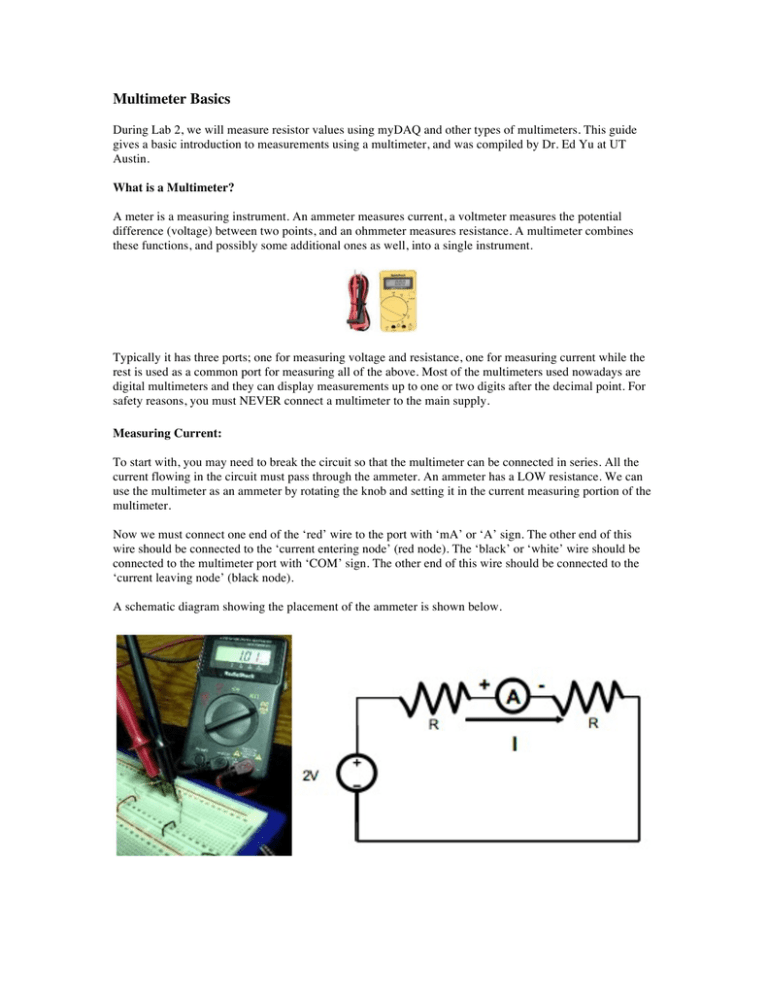
Multimeter Basics During Lab 2, we will measure resistor values using myDAQ and other types of multimeters. This guide gives a basic introduction to measurements using a multimeter, and was compiled by Dr. Ed Yu at UT Austin. What is a Multimeter? A meter is a measuring instrument. An ammeter measures current, a voltmeter measures the potential difference (voltage) between two points, and an ohmmeter measures resistance. A multimeter combines these functions, and possibly some additional ones as well, into a single instrument. Typically it has three ports; one for measuring voltage and resistance, one for measuring current while the rest is used as a common port for measuring all of the above. Most of the multimeters used nowadays are digital multimeters and they can display measurements up to one or two digits after the decimal point. For safety reasons, you must NEVER connect a multimeter to the main supply. Measuring Current: To start with, you may need to break the circuit so that the multimeter can be connected in series. All the current flowing in the circuit must pass through the ammeter. An ammeter has a LOW resistance. We can use the multimeter as an ammeter by rotating the knob and setting it in the current measuring portion of the multimeter. Now we must connect one end of the ‘red’ wire to the port with ‘mA’ or ‘A’ sign. The other end of this wire should be connected to the ‘current entering node’ (red node). The ‘black’ or ‘white’ wire should be connected to the multimeter port with ‘COM’ sign. The other end of this wire should be connected to the ‘current leaving node’ (black node). A schematic diagram showing the placement of the ammeter is shown below. Measuring Voltage: For voltage measurements, you do not need to break the circuit. To measure voltage drop across a resistor in an electrical circuit, one must connect the multimeter in parallel with that particular resistor. In this case, a multimeter behaves more like an actual voltmeter. A voltmeter has a very HIGH resistance inside it. We can use the multimeter as a voltmeter by rotating the knob and setting it in the voltage-measuring portion of the multimeter. Now we must connect one end of the ‘red’ wire to the port with ‘V’ sign. The other end of this wire should be connected to the ‘current entering node’ (red node) of the resistor. Now the ‘black’ or ‘white’ wire that often represents ‘Neutral’ should be connected to the multimeter port with ‘COM’ sign. The other end of this wire should be connected to the ‘current leaving node (black node) of the resistor. A schematic diagram showing the placement of the voltmeter is shown below. Typically, voltage measurements are used much more often than current measurements. The processing of electronic signals is usually thought of in voltage terms. It is an added advantage that a voltage measurement is easier to make. The original circuit does not need to be changed. Often, the meter probes are connected simply by touching them to the points of interest. Measuring Resistance: An ohmmeter does not function with a circuit connected to a power supply. If you want to measure the resistance of a particular component, you must take it out of the circuit altogether and test it separately. A multimeter works by passing a current through the component being tested. The pictures below show the resistance of 2 – 1 k resistors in parallel. A schematic diagram showing the placement of the ohmmeter is shown below.


