Lab D: Parallel Circuits
advertisement

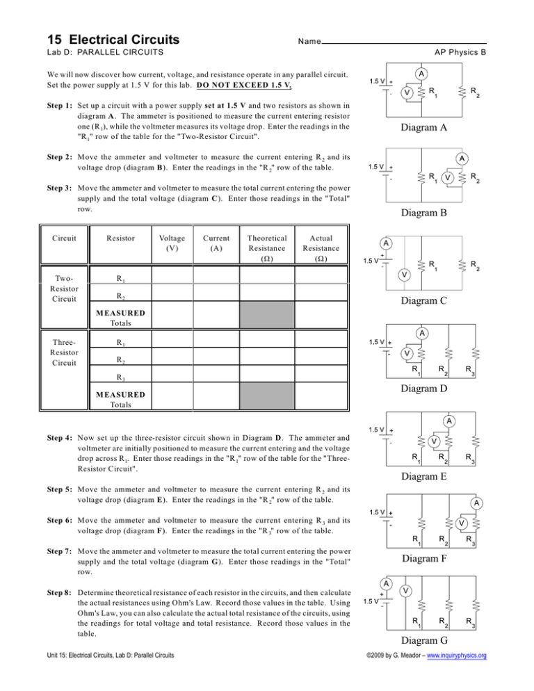
15 Electrical Circuits Nam e Lab D: PARALLEL CIRCUITS AP Physics B We will now discover how current, voltage, and resistance operate in any parallel circuit. Set the power supply at 1.5 V for this lab. DO NOT EXCEED 1.5 V. Step 1: Set up a circuit with a power supply set at 1.5 V and two resistors as shown in diagram A. The ammeter is positioned to measure the current entering resistor one (R 1), while the voltmeter measures its voltage drop. Enter the readings in the "R 1" row of the table for the "Two-Resistor Circuit". Diagram A Step 2: Move the ammeter and voltmeter to measure the current entering R 2 and its voltage drop (diagram B). Enter the readings in the "R 2" row of the table. Step 3: Move the ammeter and voltmeter to measure the total current entering the power supply and the total voltage (diagram C). Enter those readings in the "Total" row. Circuit Resistor TwoResistor Circuit R1 Voltage (V) Current (A) Theoretical Resistance (Ù) Diagram B Actual Resistance (Ù) R2 Diagram C M EASURED Totals ThreeResistor Circuit R1 R2 R3 M EASURED Totals Step 4: Now set up the three-resistor circuit shown in Diagram D. The ammeter and voltmeter are initially positioned to measure the current entering and the voltage drop across R 1. Enter those readings in the "R 1" row of the table for the "ThreeResistor Circuit". Diagram D Diagram E Step 5: Move the ammeter and voltmeter to measure the current entering R 2 and its voltage drop (diagram E). Enter the readings in the "R 2" row of the table. Step 6: Move the ammeter and voltmeter to measure the current entering R 3 and its voltage drop (diagram F). Enter the readings in the "R 3" row of the table. Step 7: Move the ammeter and voltmeter to measure the total current entering the power supply and the total voltage (diagram G). Enter those readings in the "Total" row. Step 8: Determine theoretical resistance of each resistor in the circuits, and then calculate the actual resistances using Ohm's Law. Record those values in the table. Using Ohm's Law, you can also calculate the actual total resistance of the circuits, using the readings for total voltage and total resistance. Record those values in the table. Unit 15: Electrical Circuits, Lab D: Parallel Circuits Diagram F Diagram G ©2009 by G. Meador – www.inquiryphysics.org ANSWER ALL QUESTIONS IN COMPLETE SENTENCES 1. How does the voltage drop across each resistor in the two different circuits compare with the voltage for the power supply? Contrast this to the behavior in a series circuit. 2. Your data shows how current flows through parallel circuits. Contrast this to the behavior in a series circuit. 3. How are resistance and current related in the different parts of a parallel circuit? (Does higher resistance result in higher or lower current, or does it have no effect?) 4. Adding a resistor to a series circuit increases the total resistance. Parallel circuits behave differently: compare the two total resistance values in the table. How did the total resistance change when a third resistor was added? 5. How do the total resistances compare with the individual resistances in parallel circuits? 6. There is a formula for computing the total resistance of a parallel circuit for any number of resistors. After completing all the lab questions, try to discover this formula. Use scratch paper for your work. PROPERTIES OF PARALLEL CIRCUITS 7. You can now formulate the relationships between the total and individual values for current, voltage, and resistance in any parallel circuit. Use your answers to questions 1-6 to guide you. The current: The voltage: The resistance: Unit 15: Electrical Circuits, Lab D: Parallel Circuits ©2009 by G. Meador – www.inquiryphysics.org


