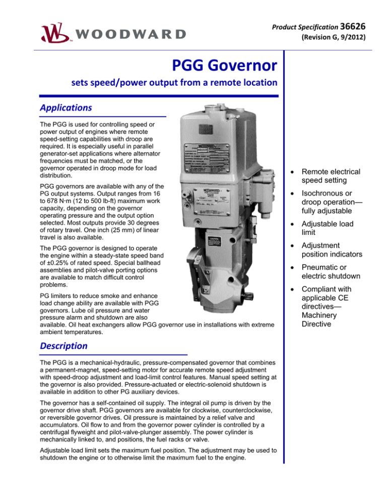
Product Specification 36626 (Revision G, 9/2012) PGG Governor sets speed/power output from a remote location Applications The PGG is used for controlling speed or
power output of engines where remote
speed-setting capabilities with droop are
required. It is especially useful in parallel
generator-set applications where alternator
frequencies must be matched, or the
governor operated in droop mode for load
distribution.
PGG governors are available with any of the
PG output systems. Output ranges from 16
to 678 Nm (12 to 500 lb-ft) maximum work
capacity, depending on the governor
operating pressure and the output option
selected. Most outputs provide 30 degrees
of rotary travel. One inch (25 mm) of linear
travel is also available.
The PGG governor is designed to operate
the engine within a steady-state speed band
of ±0.25% of rated speed. Special ballhead
assemblies and pilot-valve porting options
are available to match difficult control
problems.
PG limiters to reduce smoke and enhance
load change ability are available with PGG
governors. Lube oil pressure and water
pressure alarm and shutdown are also
available. Oil heat exchangers allow PGG governor use in installations with extreme
ambient temperatures.
Description The PGG is a mechanical-hydraulic, pressure-compensated governor that combines
a permanent-magnet, speed-setting motor for accurate remote speed adjustment
with speed-droop adjustment and load-limit control features. Manual speed setting at
the governor is also provided. Pressure-actuated or electric-solenoid shutdown is
available in addition to other PG auxiliary devices.
The governor has a self-contained oil supply. The integral oil pump is driven by the
governor drive shaft. PGG governors are available for clockwise, counterclockwise,
or reversible governor drives. Oil pressure is maintained by a relief valve and
accumulators. Oil flow to and from the governor power cylinder is controlled by a
centrifugal flyweight and pilot-valve-plunger assembly. The power cylinder is
mechanically linked to, and positions, the fuel racks or valve.
Adjustable load limit sets the maximum fuel position. The adjustment may be used to
shutdown the engine or to otherwise limit the maximum fuel to the engine.
Remote electrical
speed setting
Isochronous or
droop operation—
fully adjustable
Adjustable load
limit
Adjustment
position indicators
Pneumatic or
electric shutdown
Compliant with
applicable CE
directives—
Machinery
Directive
Woodward 36626 p.2
PGG Auxiliary Devices The PGG can be factory equipped with PG type auxiliary devices. Contact a Woodward representative for specific
advice in selecting optional features. Publications are available to describe the functioning of auxiliary features.
Heat Exchanger
A heat exchanger helps maintain governor temperature below 93 °C (200 °F). Governor temperature depends on
ambient temperature, radiation from surrounding devices, governor speed, and internal governor operating pressure.
A heat exchanger is recommended with the PGG when drive exceeds 1000 rpm at 1379 kPa (200 psi) pressure or
1300 at 690 kPa (100 psi). See manual 36641, Governor Oil Heat Exchanger.
Booster Servomotor
As an aid for quick starts, an externally-mounted booster servomotor supplies immediate oil pressure to the
governor. See manual 36684, Booster Servomotor.
Air Pressure Fuel Limiters
A manifold air pressure bias fuel limiter for turbo-supercharged engines limits engine fuel during acceleration as a
function of air-manifold or air-box pressure. It ensures more complete combustion, reduces smoke, and improves
efficiency during acceleration. See manual 36695, PG Manifold Air Pressure Bias Fuel Limiter.
Shutdown Solenoids
The electric solenoid can be equipped as de-energize or energize to shutdown. Various coils accommodate common
dc voltages. Rectifiers can be included to enable 110 or 220 Vac for shutdown. See manual 36650, Solenoid
Operated Shutdown Assembly.
An air-oil-water shutdown can be arranged to shut down with an increasing or decreasing pressure signal. See
manual 36651, Pressure Actuated Shutdown Assembly.
Automatic Safety Shutdown & Alarms
The lube oil pressure failure and water pressure failure shutdown devices automatically either shut down the engine
or trip and alarm switch when oil or water pressures fall below a safe value. See manual 36652, Automatic Safety
Shutdown and Alarms.
Specifications Speed Setting
Speed Setting Motor
Speed Setting Voltage
Rate of Speed Change
Position Indicator Lights
Mating Electric Connector
Manual Speed Setting
Max-Min Position Stops
Permanent magnet type motor. At rest, the motor acts as a brake to resist
speed change due to vibration. A revolution counter shows speed-setting
position (zero is idle).
24 Vdc, ±6 V. Polarity is reversed to raise and lower the speed setting. This
is accomplished by customer supplied wiring and DPDT switch.
Typically 730 rpm/min at 24 Vdc
Customer supplied wiring may include maximum and minimum indicator
lights with the DPDT speed setting switch. Switch contacts in the PGG are
provided.
14 pin
A friction clutch included in the speed-setting motor drive provides manual
speed setting through an adjustment knob on the governor.
Integral micro-switches are factory adjusted to stop the speed-setting motor
at specified max and min speeds. Positive mechanical stops are provided
for manual speed setting.
Droop Adjustment
Droop
Droop Stop
Using 270° maximum rotation of the droop adjusting knob (and with typical
PG speeder spring and flyweights), droop is infinitely adjustable from 0 to
100 rpm maximum for the full governor stroke.
A positive, minimum position stop provides zero droop at zero droop
indicator position (0). Maximum droop is at 10 indicator position.
Set zero droop on independent units to allow load change without changing
speed. On applications where prime movers drive the same shaft or are in
parallel in an electrical system, droop must be used and automatically
divides and balances load between units. If one unit in the system has the
capacity, its governor may be set for zero droop to regulate the frequency of
the prime mover system and handle all load changes.
Woodward 36626 p.3
Load Limit Adjustment
Load Limit
Dial adjustment limits governor power cylinder output to increase fuel.
Adjustable from no limiting to shutdown.
Governor Output
Woodward recommends use of 60 to 70% travel from no load to full load.
Composition/Weight
Construction
Weight
Case and base are cast iron, internal parts are mild and case hardened
steels.
39 to 54 kg (85 to 120 lb) depending on auxiliary devices and work output of
79 Nm (58 lb-ft) or less. 271 to 678 Nm (200 to 500 lb-ft) governors can
weigh in excess of 227 kg (500 lb).
Governor Drive
Drive Shaft
Rotation
Speed Range
Drive Shaft Power
1.125-48 serration is standard. Splined or keyed shafts are optional.
Fixed clockwise, fixed counterclockwise, or reversible. Fixed rotation
required for governor speed in excess of 1000 rpm.
Maximum speed range is 200 to 1600 rpm. 250 to 1000 is the
recommended speed range. Oil coolers may be required for governor
operation at speeds in excess of 1000 rpm. (All speeds are governor drive
speeds, not engine speeds.)
Drive power for different types of PG governors will vary depending upon
speed, internal pump pressure, pump volumetric displacement, pump
efficiency, and oil viscosity. Contact Woodard if further information is
required.
Hydraulic Supply
Oil Requirements
Ambient Temperature
Operating Pressure
SAE 10 to 50, depending on operating temperature. 100 to 200 SUS
viscosity at operating temperature. Self-contained sump.
–29 to +99 °C (–20 to +210 °F). Oil coolers may be required at upper
ambient temperature limits. Hydraulic oil in governor must be matched to
operating temperatures.
690 kPa (100 psi) standard. 896 and 1379 kPa (130 and 200 psi) optional
for increased work output. 1379 kPa (200 psi) governors often require oil
coolers.
Installation
Mounting Base
Configuration
Various base configurations are available. See Woodward manual 36693,
PG Base Assemblies.
Vertical
Regulatory Compliance
Other European Compliance:
Machinery Directive
Compliant as partly completed machinery per 2006/42/EC.
Woodward 36626 p.4
PGG Governor Outline Drawing (Do not use for construction)
For more information contact:
PO Box 1519, Fort Collins CO, USA 80522-1519
1000 East Drake Road, Fort Collins CO 80525
Tel.: +1 (970) 482-5811 Fax: +1 (970) 498-3058
www.woodward.com
Distributors & Service
Woodward has an international network of distributors and service facilities.
For your nearest representative, call the Fort Collins plant or see the
Worldwide Directory on our website.
This document is distributed for informational purposes only. It is not to be construed as
creating or becoming part of any Woodward contractual or warranty obligation unless
expressly stated in a written sales contract.
Copyright © Woodward 1978–2012, All Rights Reserved

