Low frequency sweep control with Nomad-65, VE464 and
1
Low frequency sweep control with Nomad-65, VE464 and CheckSweep
Daniel BOUCARD, Gilles OLLIVRIN & Denis MOUGENOT
Sercel, France
Only about half of the seismic crews worldwide are equipped with vibrators, but these crews produce more than three quarters of the seismic records. Such performance is related to the high source productivity that several fleets of vibrators sweeping alternatively and/or simultaneously made it possible. More than often these fleets are composed of a few heavy vibrators of 60,000lbf or more hydraulic peak force like Sercel Nomad-65. Thanks to their mechanical and hydraulic performances, such heavy vibrators offer the capability to widen the frequency bandwidth of the signal. Due to the strong absorption of the high frequencies, their propagation may be limited to the shallow levels, but on the low frequency side their use has been very beneficial to the seismic imaging at all depths of investigation. Emitting these low frequencies (down to 1Hz) requires tuning the Pilot sweep taking vibrator limitations into account.
In this article, we describe what we think is today the most reliable way to generate low frequencies. It is a combination of Nomad-65, a heavy vibrator designed for low frequency performances, of VE464 the latest generation of vibrator electronics, and of CheckSweep a piece of software to verify the designed sweep in simulation before to go to the vibrator. The benefits of such successful combination are presented at the end to illustrate the contribution of the low frequencies to the improvement of a 3D seismic image.
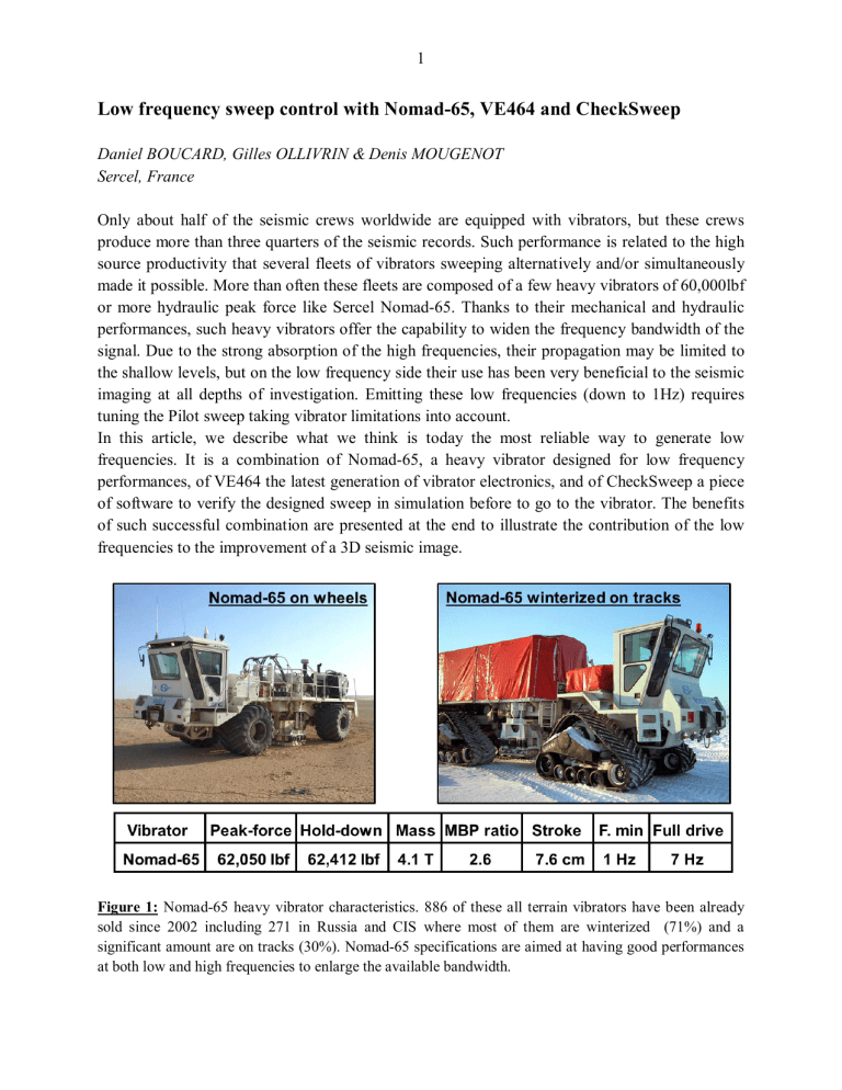
Figure 1: Nomad-65 heavy vibrator characteristics. 886 of these all terrain vibrators have been already sold since 2002 including 271 in Russia and CIS where most of them are winterized (71%) and a significant amount are on tracks (30%). Nomad-65 specifications are aimed at having good performances at both low and high frequencies to enlarge the available bandwidth.
2
The Nomad-65 heavy vibrator
With no doubt, Nomad-65 is the most popular of the heavy vibrators particularly in Russia and
CIS. It is inherited from technologies developed in the USA by Mertz for the so successful
M26HD with in mind developing an all-terrain high performance vibrator using updated design.
Nomad-65 offers the possibility to move from wheels to track and vice-versa (Figure 1). For operations in cold conditions, two winterization levels (-30°C & -50°C) are available based on additional heaters and a vibrator canopy. For surveys in inhabited areas, a soundproof case can encapsulate the engine and hydraulic pumps assembly and narrow axels may reduce its width to
2.5m. As a result of a cooperation between Sercel and Thomas Constructeurs, Nomad-65 shaker has been fit on a specially design 8x8 off-road Renault Dxi11 truck. This "Thomas vib 3246 8x8" complies with European regulations for emission and road circulation (max speed: 85 km/h).
To date (August 2013), 886 Nomad have been sold to 55 end-users in 30 different countries. The earliest ones were delivered by end 2002 in Russia (VolgogradNefteGeofizika) and CIS
(Turkmenistan). From the 271 in Russia and CIS, 81 are on tracks (30%), 69 are winterized -
30°C (25%) and 124 -50°C (46%). Nomad-65 actuator is designed with the highest mass-tobaseplate ratio (2.62) in the 60,000lbs vibrator market and a completely redefined hydraulics. Oil accumulators have been placed as close as possible to the actuator to provide the necessary hydraulic flow when starting sweeping. The lift system is based on two heavy duty columns and the uniformly distributed hold-down is directly applied on top of the shaker to avoid rocking motions and associated distortion.
Figure 2: Parameters from which a stable estimate of the Ground Force (GF) may be defined using the weighted sum of the acceleration of the reaction mass (ACm) and of the baseplate (ACp) by the mass of the reaction mass (Mm) and of the baseplate (Mp): GF = (Mm x ACm) + (Mp x ACp). At low frequency
(4Hz in this example), GF is equivalent to the contribution of the mass (Mm x ACm) since ACp is small as well as Mp compared to Mm.
3
The challenge of emitting low frequencies
A stable and real-time estimation of the signal emitted by a vibrator (the Ground Force) is to consider it as the sum of the force emitted by the reaction mass and by the baseplate (J. J. Sallas,
1984). Knowing the mass of the reaction mass (Mm) and of the baseplate (Mp) it is just required to know their respective accelerations (ACm & ACp) to compute the Ground Force (Figure 2):
GF = (Mm x ACm) + (Mp x ACp). This information is obtained by fixing one accelerometer directly on the reaction mass and on the baseplate. If required, a more accurate estimation of these values can be obtained by using several accelerometers in order to correct from the possible torsion of the moving parts of the actuator.
Recording these two accelerations shows that their contribution varies depending on the frequency of the sweep and on the ground characteristics: at low frequencies, the acceleration of the reaction mass is significant compared to the one of the baseplate and this reverses towards the high frequencies. Thus, at low frequency (LF) the Ground Force gets similar to the force of the reaction mass (Mm x ACm; Figure 2). Since the ACm depends on the displacement of the reaction mass (or stroke) which is a few centimeters, the Ground Force is limited. This may be compensated by a heavier mass (Mm). Thus, like with Nomad-65, heavier is the mass (4.1T) and longer is the stroke (7.6 cm) higher is the force at low frequency.
Because of the hydraulics, vibrators have other limitations (J. J. Sallas, 2010). At the start of a low frequency sweep, there is a steep increase in the required flow (from 0 to maximum) that cannot be delivered by the pump in such limited time. To avoid supply pressure to drop that may limit mass acceleration, two accumulators were added to the Nomad-65 actuator to quickly handle the necessary fluid flow. A last but less severe limitation is coming from the main valve that directly drives the piston and can only accept a limited amount of fluid.
These different low frequency limitations can be expressed as numerical equations depending on the vibrator characteristics (Mm, mass & valve stroke, max. pump & valve flows, piston surface).
These equations define the maximum force related to the pump, the stroke and the valve as a function of the frequency (Figure 3). They are all bounded by the general force limit of the vibrator that is the minimum of the hold-down and of the hydraulic peak-force (62,050lbf for
Nomad-65). The drive is the percentage of the maximum force produced by the vibrator that we will use to not deteriorate the vibrator and create too much distortion. This drive mainly depends on the ground characteristics and of the frequency.
To emit low frequencies, the Pilot must fit with all these limitations. If the pump flow looks as the more constraining limitation (red curve; Figure 3), in fact it is not, thanks to the accumulators
(black arrow; Figure 3). Due to its response time, the pump provides the mean flow while the accumulators provide the required instantaneous flow. The actual limitation is mechanical: it is the stroke of the reaction mass (blue curve; Figure3). The intersection of this curve with the peak force limit defines the minimum frequency that may be sustained at full drive which is slightly below 7Hz for Nomad-65. This diagram of the vibrator limitation evidences that lower is this drive lower will be the start frequency that may be used without reaching the limits. Thus, it is possible to start sweeping from 1Hz providing that the drive is low enough. This reduction of the drive and thus of the force could be compensated by spending more time to get the same
4 amplitude at all frequencies (flat spectrum).
However, the time to spend function of the frequency
(sweep rate) is not varying linearly: the amplitude is proportional to the drive, but it is only proportional to the square of the time spent at each frequency . Thus, dividing the drive per two requires spending four times more and by four sixteen times more… Such non-linear taper where the sweep rate toward the low frequencies increases is called a low dwell sweep.
Figure 3: Overview of the methodology used to control the compatibility of a low dwell Pilot sweep with the vibrator characteristics. From the vibrator specifications and using physical equations the mechanical and hydraulic vibrator limitations are defined. To compensate from a lower drive, the time spent at low frequency is significantly increased at least as the square of the reduction factor of the drive. After having input such non-linear low-dwell sweep into the CheckSweep QC software, their compatibility with the vibrator can be tested. Then, a field trial should be performed to verify this compatibility on each vibrator equipped with a VE464.
As we can see, starting to sweep at very low frequency may be quite penalizing, the duration of the taper increasing significantly depending of the start frequency (e.g. green LF sweeps from 1,
2 or 3Hz; Figure 4). This is detrimental for the duration of the sweep and thus for the productivity. With a heavy vibrator, like Nomad-65 equipped with a long stroke, accumulators in the actuator, efficient pumps and valve, this time may be significantly reduced as long as we are able to design a taper as close as possible to the vibrator limits. Such design is explains in several
5 publications (J. J. Sallas, 2010. J. Wei and T. F. Phillips, 2013). It is also protected by patents: e.g. MD sweep for Schlumberger (C. Bagaini, 2008); EmphaSeis for CGG (G. Beaten et al.,
2010). Sercel provides a piece of software made available to the users of VE464 to check that the
Pilot sweep they have designed fits with the limitations of their vibrator (this is valid for any type of vibrators, providing their specifications are known).
Figure 4: Example of different low dwell sweeps (in green) designed for Nomad-65 and starting from increasing low frequencies (1-2-3Hz from left to right) up to 85Hz. Just shifting of 1Hz significantly increases the taper duration. Using another vibrator, not as dedicated to low frequencies than Nomad-65, would increase even more this time. Assuming a fixed 12s sweep length, the time spent at full drive (from
7 to 85Hz) varies significantly and thus the associated amplitude as seen on the amplitude spectra.
Comparison, is done with linear sweeps (in blue) starting from the same frequency and having the same duration at full drive than the corresponding non-linear sweeps. Their corresponding amplitude spectra lack of the lowest frequencies and demonstrate the interest of using non-linear tapers.
Low frequency Pilot sweep QC with CheckSweep
Checksweep runs under Windows in a single window template. It is used to design a sweep
(duration of start and end tapers, initial phase, tables of Amplitude vs. Time and Frequency vs.
Time; Figure 5) or to input a custom sweep the same way as for VE464. Several sweeps may be compared in different domains: Frequency vs. Time, Amplitude vs. Time (sweep and drive),
Amplitude vs. Frequency (spectrum) as well as by the Correlation wavelet vs. Time. Vibrator
6 characteristics are input from a text file. After having set the ground parameters (cut-off frequency and ground damp factor defined from a plot of ACp vs. ACm), the minimum frequency for the stroke, the valve and the pump are computed and they may be compared between vibrators or drive levels. Once a vibrator and the drive have been selected, it becomes possible to compare for different sweeps (including three simultaneously in different colors) and at different time (and thus frequency): the reaction mass displacement (cm) compared to the usable stroke; the main valve displacement (mm) compared to 0.9 of the usable stroke; the instantaneous valve flow (gpm) compared with the maximum pump flow and the maximum valve flow; the differential pressure (psi) between the supply pressure and the return pressure compared to the vibrator supply pressure limit (Figure 5).
Figure 5: The graphic user interface of CheckSweep, Sercel QC software running under Windows. The left part is to create or input a sweep the same way as it is done in the VE464. The selected sweep is displayed. On the upper right hand side, it is possible to compare up to three sweeps in different domains.
Below, it is possible to select different vibrators using different drives as well as to set the ground characteristics. From these parameters, the limits of the vibrator are displayed and compared in different domains with the corresponding characteristics of the sweep. Red arrows show that the linear sweep (2-
85Hz, 8.5s in blue) does not fit with the usable stroke and valve flow like the non-linear (2-85Hz, 12s in green) does.
7
The selected sweep should ideally fit closely to the vibrator limits to not spend too long in the non-linear taper. Then, it should be field tested by each vibrator which characteristics are in practice unique (depending on maintenance, aging…). Any overload that may occur on the mechanics or the hydraulics would then be warned by VE464 with a specific message (F: hold down weight, P: supply pressure; M: mass limit position, V: valve limit position; E: command at maximum). This shows the importance of the vibrator electronics (VE) particularly a low frequency to control the Ground Force as it is emitted at conditions close to the limits of the vibrators at which distortion becomes significant.
Low frequency Ground Force control by VE464
Like all vibrator electronics, VE464 is made of two parts communicating by radio. The Digital
Pilot Generator (DPG) is the part connected to the data acquisition system (428XL or other type).
It permits to design any kind of digital Pilot (linear, logarithmic, compound, pulse…). It is also possible to import a custom sweep as defined by external tools (Excel, MATLAB) as it is often the case for the non-linear sweeps. Considering low frequencies, special mention should be made of the random sweep automatically designed by VE464 in which the different frequencies are randomly distributed. By spreading the low frequencies over the sweep length, this avoids the limits of the vibrator to be reached and reduces possible damages in inhabited areas.
Installed in each vibrator, the VE464 Digital Servo Drive (DSD) performs a real-time comparison of the Ground Force with the Pilot. The classic feedback loop that controls and corrects the phase only at the GF zero-crossing becomes inefficient at low frequency due to the increasing sweep period and to the noise level. Thanks to its full digital control based on a numerical vibrator model (D. Boucard & G. Ollivrin, 2010) VE464 servo-control is designed to perform a pursuit command to drive every 0.25ms the Ground Force as close as possible of the Pilot. Since nonlinearity's are included in the vibrator model, the commands take them into account to provide a non-linear input that reduces harmonic distortion. This is particularly critical a low frequency particularly below 3-4Hz, where all non-linearity's and the associated distortion increase.
However, because non-linear tapers increase the sweep rate, correlation is able to reject this distortion at larger negative times. Thus, we can state that in the methodology proposed for low dwell sweep, distortion should not be an issue (T. Bianchi, personal communication): lower is the frequency, more is the distortion but larger is the negative time at which it will be rejected after correlation.
A case study in South Africa
The capability of Nomad-65 to emit very low frequencies using a low dwell sweep (EmphaSeis) has been again illustrated by the recent case (2012) of a dense 3D acquisition survey (1.92 million traces /km²) over a gold mine in South Africa (M. Denis et al., 2013). This survey is compared with a previous conventional 3D acquisition (32,000 traces /km²) recorded in 1996 with a standard linear 10-90Hz sweep. On the migrated sections (Figure 6), the benefit of performing a dense source grid (50m x 50m) is confirmed by an outstanding image quality from shallow to deep targets (down 4 km). The broadband sweep (3-160Hz) emitted by three Nomad-
8
65 vibrators was able to achieve a remarkable seismic wavelet compression. By low cut filtering below 10Hz the final pre-stack time migrated data, the contribution of the low frequencies is highlighted: the general character of the image is improved with better differentiation of the reflectivity sequences, each with a different texture; at the limits of the reflection-free sequence, it is obvious (red arrows, Figure 6) that the side lobes of the seismic wavelet are missing which illustrates the capability of the low frequencies at improving vertical resolution. Overall, this broadband section provides unprecedented stratigraphic details.
Figure 6: Comparison of vertical sections coming from a conventional 3D (10-90Hz, 32,000 traces /km²) compared to a dense UltraSeis 3D (1.92 million traces /km²) recorded from broadband sources (3 Nomad-
65 using a 3-160Hz EmphaSeis sweep). These 3Ds were shot over a gold mine in South Africa (M. Denis et al., 2013; courtesy Anglo Gold Ashanti and Vaughan Chamberlain). Left and right sections show the tremendous improvement of both the imaging and the vertical resolution related to the dense broadband survey. The middle section is the new survey after low cut filtering below 10Hz to highlight the contribution of the low frequencies: layer texture and side lobe wavelet removal (see red arrows).
Low frequencies not only enhance resolution, but being less sensitive to absorption and diffractions they also improve penetration. They give access, via seismic inversion, to the long period (LF) vertical variations of the subsurface layers and they provide an evaluation of the absolute values of their acoustic properties which does not rely on well data. As an example, the benefit of using the lowest possible frequencies to derive an accurate velocity model of the subsurface has been confirmed by full wave inversion to (G. Beaten et al., 2013). Low
9 frequencies are also more sensitive to fluid variations in the porous volume of the rocks which makes their use beneficial to any 4D seismic monitoring project.
For long time emitting such low frequencies has been avoided, the main reason being the inability of the previous vibrators to emit and control them. People were also reluctant to reinforce ground roll that was difficult to remove particularly when it was aliased. Software was not (and is still often not) designed to process low frequency signal. Things have changed and using low frequencies today is a requirement by many oil companies, like in the Middle East (S.
Mahrooqi et al., 2012). However, recording very low frequencies (down 1-2 Hz) is still challenging for various reasons including the use of 10Hz geophones that respond with a -
12dB/octave attenuation below their resonant frequency. This is to overcome these limitations that heavy vibrators, like Nomad-65, have been conceived and that digital MEMS accelerometers
(e.g. DSU) and low frequency geophone (e.g. SG-5) are also proposed.
Acknowledgments
The authors are very grateful to Anatoly Cherepovskiy and Ramil Zakirov for translating our manuscript in Russian while preforming a useful review. We also thank Anglo Gold Ashanti and especially Vaughan Chamberlain and Michel Denis for the opportunity to reproduce the case study.
Bibliography
- Bagaini, C., 2008. Low-frequency vibroseis data with maximum displacement sweeps. The
Leading Edge, 27, p.582-591.
- Baeten, G., A. Egreteau, J. Gibson, F. Lin, P. Maxwell, and J. J. Sallas, 2010. Low-frequency generation using seismic vibrators. 72nd Annual International Conference and Exhibition, EAGE,
Extended abstracts.
- Baeten, G., F. ten Kroode, S. Rawahi, and S. Mahrooqi, 2013. Onshore Low Frequency
Acquisition for Full Waveform Inversion - from Field Trials to State of the Art Production
Surveys. 75th Annual International Conference and Exhibition, EAGE, Workshop paper I07.
- Boucard, D. and G. Ollivrin, 2010. Development in vibrator control. Geophysical
Prospecting, 58, p.33-40.
- Denis, M., V. Brem, and F. Pradalie, 2013. Is Broadband Land Seismic as Good as Marine
Broadband? 75th Annual International Conference and Exhibition, EAGE, Workshop paper I08.
- Mahrooqi, S., S. Rawahi, S. Yarubi, A. Yahyai, K. Hunt, F. Clow, and I. Vincent, 2012.
Cracking very LF land seismic acquisition - A step change. 74th Annual International Conference and Exhibition, EAGE, Extended abstracts.
- Sallas, J. J., 1984. Seismic vibrator control and the downgoing P-wave. Geophysics, 49, p.732–740.
- Sallas, J. J., 2010. How do hydraulic vibrators work? A look inside the black box.
Geophysical Prospecting, 58, p.3-18.
- Wei, Z., and T. F. Phillips, 2013. On the generation of low frequencies with modern seismic vibrators, Geophysics, 78, 2, p. 91-97.
