SGD
Spark Gap Diverter
Features
• Effective
equipotential
bonding – provides
N-E protection
bond on TT power
distribution systems
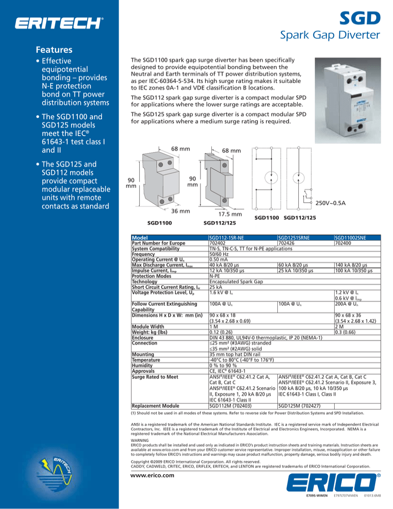
The SGD1100 spark gap surge diverter has been specifically
designed to provide equipotential bonding between the
Neutral and Earth terminals of TT power distribution systems,
as per IEC-60364-5-534. Its high surge rating makes it suitable
to IEC zones 0A-1 and VDE classification B locations.
• The SGD1100 and
SGD125 models
meet the IEC®
61643-1 test class I
and II
The SGD125 spark gap surge diverter is a compact modular SPD
for applications where a medium surge rating is required.
• The SGD125 and
SGD112 models
provide compact
modular replaceable
units with remote
contacts as standard
The SGD112 spark gap surge diverter is a compact modular SPD
for applications where the lower surge ratings are acceptable.
68 mm
68 mm
90
mm
90
mm
250V~0.5A
36 mm
SGD1100
17.5 mm
SGD1100 SGD112/125
SGD112/125
Model
Part Number for Europe
System Compatibility
Frequency
Operating Current @ Un
Max Discharge Current, Imax
Impulse Current, Iimp
Protection Modes
Technology
Short Circuit Current Rating, Isc
Voltage Protection Level, Up
SGD112-1SR-NE
SGD1251SRNE
702402
702426
TN-S, TN-C-S, TT for N-PE applications
50/60 Hz
0.50 mA
40 kA 8/20 μs
60 kA 8/20 μs
12 kA 10/350 μs
25 kA 10/350 μs
N-PE
Encapsulated Spark Gap
25 kA
1.6 kV @ In
Follow Current Extinguishing
Capability
Dimensions H x D x W: mm (in)
100A @ Un
Module Width
Weight: kg (lbs)
Enclosure
Connection
Mounting
Temperature
Humidity
Approvals
Surge Rated to Meet
Replacement Module
100A @ Un
SGD11002SNE
702400
140 kA 8/20 μs
100 kA 10/350 μs
1.2 kV @ In
0.6 kV @ limp
200A @ Un
90 x 68 x 18
90 x 68 x 36
(3.54 x 2.68 x 0.69)
(3.54 x 2.68 x 1.42)
1M
2M
0.12 (0.26)
0.3 (0.66)
DIN 43 880, UL94V-0 thermoplastic, IP 20 (NEMA-1)
≤25 mm² (#3AWG) stranded
≤35 mm² (#2AWG) solid
35 mm top hat DIN rail
-40°C to 80°C (-40°F to 176°F)
0 % to 90 %
CE, IEC® 61643-1
ANSI®/IEEE® C62.41.2 Cat A,
ANSI®/IEEE® C62.41.2 Cat A, Cat B, Cat C
Cat B, Cat C
ANSI®/IEEE® C62.41.2 Scenario II, Exposure 3,
ANSI®/IEEE® C62.41.2 Scenario 100 kA 8/20 μs, 10 kA 10/350 μs
II, Exposure 1, 20 kA 8/20 μs IEC 61643-1 Class I, Class II
IEC 61643-1 Class II
SGD112M (702403)
SGD125M (702427)
(1) Should not be used in all modes of these systems. Refer to reverse side for Power Distribution Systems and SPD Installation.
ANSI is a registered trademark of the American National Standards Institute. IEC is a registered service mark of Independent Electrical
Contractors, Inc. IEEE is a registered trademark of the Institute of Electrical and Electronics Engineers, Incorporated. NEMA is a
registered trademark of the National Electrical Manufacturers Association.
WARNING
ERICO products shall be installed and used only as indicated in ERICO’s product instruction sheets and training materials. Instruction sheets are
available at www.erico.com and from your ERICO customer service representative. Improper installation, misuse, misapplication or other failure
to completely follow ERICO’s instructions and warnings may cause product malfunction, property damage, serious bodily injury and death.
Copyright ©2009 ERICO International Corporation. All rights reserved.
CADDY, CADWELD, CRITEC, ERICO, ERIFLEX, ERITECH, and LENTON are registered trademarks of ERICO International Corporation.
www.erico.com
E709S-WWEN
E797LT07WWEN
01013.6M8
Power Distribution Systems
and SPD Installation
The IECSM 60364 series of standards characterizes low-voltage distribution
systems by their grounding method and the arrangement of the neutral and
protective earth conductors. The selection of SPDs must consider among
other issues, the level of over-voltage that may temporarily occur within the
distribution system due to ground faults. IEC 61643-12 details the temporary
over-voltages that may occur during fault conditions for these systems. To
conform with European wiring rules an SPD with a Uc rating equal to, or
greater than, this value should be selected. Effective protection does not
require SPD s to be installed in all the modes detailed. The following diagrams
provide guidance on the selection and installation of SPDs on the more
common distribution systems. While three phase WYE systems are shown,
similar logic can be applied to single phase, delta and other configuration
sources.
TN-C System
TN-S System
In the TN-C System, the neutral and protective earth conductor combine
in a single conductor throughout the system. All exposed-conductiveparts are connected to the PEN conductor.
Main
Distribution Board
Sub/Branch
Distribution Board
* Install fuse A if supply fuse B
exceeds back-up overcurrent
protection rating
* Install fuse C if supply fuse D
exceeds back-up overcurrent
protection rating
Source
Uo = Line to neutral voltage of the system
Un = Nominal country specific system voltage (typically Uo x 1.10)
In the TN-S System, a separate neutral and protective earth conductor are
run throughout. The protective PE conductor can be the metallic sheath
of the power distribution cable or a separate conductor. All exposedconductive-parts of the installation are connected to this PE conductor.
Source
Main
Distribution Board
* Install fuse A if supply fuse B
exceeds back-up overcurrent
protection rating
Sub/Branch
Distribution Board
* Install fuse C if supply fuse D
exceeds back-up overcurrent
protection rating
SPDs shown connected L-N and N-PE.
May also be connected L-PE and N-PE.
TN-C-S System
In the TN-C-S System, a separate neutral and protective earth combine in
a single PEN conductor. This system is also known as a Multiple Earthed
Neutral (MEN) system and the protective conductor is referred to as the
Combined Neutral Earth (CNE) conductor. The supply PEN conductor is
earthed at a number of points throughout the network and generally as
close to the consumer’s point-of-entry as possible. All exposed-conductiveparts are connected to the CNE conductor.
Source
Main
Distribution Board
* Install fuse A if supply fuse B
exceeds back-up overcurrent
protection rating
Sub/Branch
Distribution Board
* Install fuse C if supply fuse D
exceeds back-up overcurrent
protection rating
SPDs shown connected L-PE and N-PE.
May also be connected L-N and N-PE.
www.erico.com
TT System
A system having one point of the source of energy earthed and the
exposed-conductive-parts of the installation connected to independent
earthed electrodes.
Main
Distribution Board
Sub/Branch
Distribution Board
* Install fuse A if supply fuse B
exceeds back-up overcurrent
protection rating
* Install fuse C if supply fuse D
exceeds back-up overcurrent
protection rating
Source


