PHYSICS II: Kirchhoff`s Rules
advertisement
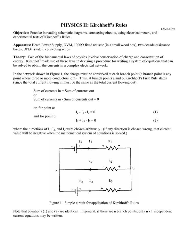
PHYSICS II: Kirchhoff’s Rules LAM 2/15/99 Objective: Practice in reading schematic diagrams, connecting circuits, using electrical meters, and experimental tests of Kirchhoff’s Rules. Apparatus: Heath Power Supply, DVM, 1000Ω fixed resistor [in a small wood box], two decade-resistance boxes, DPDT switch, connecting wires Theory: Two of the fundamental laws of physics involve conservation of charge and conservation of energy. Kirchhoff made use of these laws in devising a procedure for writing a system of equations that can be solved to obtain the currents in a complex electrical network. In the network shown in Figure 1, the charge must be conserved at each branch point (a branch point is any point where three or more conductors join). Thus, at branch points a and b, Kirchhoff's First Rule states (since the total current flowing in must be the same as the total current flowing out): Sum of currents in = Sum of currents out or Sum of currents in - Sum of currents out = 0 or, for point a: I2 - I 1 - I 3 = 0 (1) I1 + I3 - I2 = 0 (2) and for point b: where the directions of I1, I2, and I3 were chosen arbitrarily. (If any direction is chosen wrong, that current value will be negative when the mathematical system of equations is solved.) Figure 1. Simple circuit for application of Kirchhoff's Rules Note that equations (1) and (2) are identical. In general, if there are n branch points, only n - 1 independent current equations may be written. For any closed path (or loop) in the circuit of figure 4, energy gains and losses must be the same. Thus, for any closed path, Kirchhoff's Second Rule states: Sum of the EMF's = Sum of the IR losses or Sum of potential gains - Sum of potential losses = 0 For the top rectangular loop, starting clockwise at point a: +E1 - V1 - V2 = 0 (3a) +E1 - R1I1 - R2I2 = 0 (3b) or and, for the bottom rectangular loop, starting clockwise at point b: +V3 - E3 + V2 = 0 (4a) +R3I3 - E3 + R2I2 = 0 (4b) or Another equation may be obtained by starting clockwise at point a around the outside rectangular loop, as: +E1 - V1 + V3 - E3 = 0 (5a) +E1 - R1I1 + R3I3 - E3 = 0 (5b) or However, equation (5) is not independent, but is the sum of equations (3) and (4). In general, application of Kirchhoff's Rules requires: a) Label the voltage sources b) Choose and label an arbitrary current direction in each distinct path in the network, for a total of N unknown currents. b) Indicate polarities for each circuit component. c) Write n - 1 current equations for the network (containing n branches.) d) Write N - (n - 1) independent voltage equations for the network. e) Solve the system for the N unknown currents. Equations (1), (3b), and (4b) may be solved using Cramer's Rule to yield: I1 = [E1(R2 + R3) - E3R2]/D (6) I2 = [E1R3 + E3R1]/D (7) I3 = [E3(R1 + R2) - E1R2]/D (8) D = R1R2 + R1R3 + R2R3 (9) where Procedures: 1. Before connecting the circuit, turn on the power supply and adjust output A to 10 volts & then turn off the power supply. Also set the decade box values to R1≈500Ω, & R3≈800Ω and use the ohm scale of your DVM to carefully measure R1, R2 & R3 [generally your FLUKE DVM is more accurate than the decade boxes]. Then turn off the power supply and connect the circuit as in Figure 2, carefully observing polarities. Have your instructor check your connections. Use the 5V supply and output A -> Do Not use output B (it won't work in this circuit). [Note: The fixed 1000Ω resistor (R2) is only within 5% of stated value, you must use the measured values in the calculations.] Figure 2. Kirchhoff's Rules Experimental Circuit 2. Turn on the power supply, close the switch and measure V10, V5 (this may not be exactly 5V), V500, V1000, and V800. Record these values with their polarities on a circuit diagram like Figure 5. 3. Open the switch and turn off the power supply. 4. Check to verify that energy is conserved by verifying equations (3a) and (4a) (Kirchhoff's Second Rule). Notify your instructor if you have trouble. 5. Compute I500, I1000, and I800 by Ohm's Law (I = V/R & actual R values) and show that Kirchhoff's First Rule is satisfied. (Equation (1) and Equation (2)). 6. Use equations (6) - (9) to solve for the theoretical values of I500, I1000, and I800. Compare and comment on the two sets of values for the I's. Note that the multimeter is ± 1/2%, and the connecting wire resistance is negligible. ************************************************************************************* Your report should include schematic diagram with all values, experimental calculations, and a concluding paragraph on sources of error and other comments about this experiment.
