APPLICATION NOTE
Output Filter Design for EMI Rejection of the AAT5101 Class D Audio Amplifier
The AAT5101 is a high efficiency, 2.5W mono class D audio power amplifier. It can be used in portable devices, such
as MP4s, cell phones, laptops, GPS and PDAs. The device can work as a filterless class D amplifier that can operate with
a speaker directly. This application note illustrates when to use an output filter and demonstrates two types of output
filters for those who need an output filter beyond the Class D amplifier as a system design recommendation.
Why Use an Output Filter?
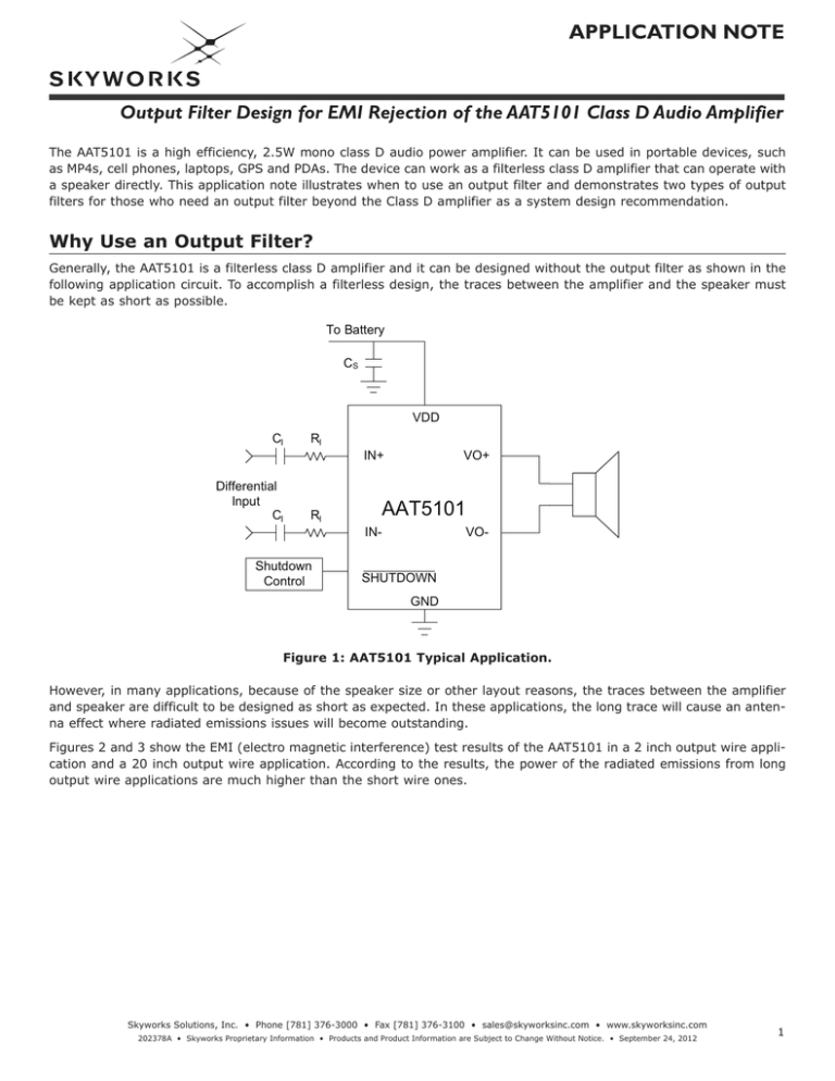
Generally, the AAT5101 is a filterless class D amplifier and it can be designed without the output filter as shown in the
following application circuit. To accomplish a filterless design, the traces between the amplifier and the speaker must
be kept as short as possible.
To Battery
CS
VDD
CI
RI
Differential
Input
CI
RI
Shutdown
Control
IN+
VO+
AAT5101
IN-
VO-
SHUTDOWN
GND
Figure 1: AAT5101 Typical Application.
However, in many applications, because of the speaker size or other layout reasons, the traces between the amplifier
and speaker are difficult to be designed as short as expected. In these applications, the long trace will cause an antenna effect where radiated emissions issues will become outstanding.
Figures 2 and 3 show the EMI (electro magnetic interference) test results of the AAT5101 in a 2 inch output wire application and a 20 inch output wire application. According to the results, the power of the radiated emissions from long
output wire applications are much higher than the short wire ones.
Skyworks Solutions, Inc. • Phone [781] 376-3000 • Fax [781] 376-3100 • sales@skyworksinc.com • www.skyworksinc.com
202378A • Skyworks Proprietary Information • Products and Product Information are Subject to Change Without Notice. • September 24, 2012
1
APPLICATION NOTE
Output Filter Design for EMI Rejection of the AAT5101 Class D Audio Amplifier
Figure 2: AAT5101 EMI Test Result with 2" Twisted-Pair Wire Connected to a 4Ω Speaker.
Figure 3: AAT5101 EMI Test Result with 20" Twisted-Pair Wire Connected to a 4Ω Speaker.
How is EMI (Electro Magnetic Interference) Radiation Generated?
A Class D amplifier uses a PWM signal to drive the output driver after the audio signal by comparing it with an internal
saw tooth waveform. The radiated noise comes from the PWM switching noise caused by the fast rising and falling edges
of the PWM square-wave. To reduce the noise in the system application, output filtering is necessary.
Choosing an Output Filter
There are two types of output filters: ferrite bead filters and LC filters.
Ferrite Bead Filter
If there is high frequency EMI sensitive circuits in the system, a ferrite bead filter connected after the class D outputs
is recommended as shown in Figure 4. The ferrite bead is specified with the feature of high impedance at high frequencies, but very low impedance at low frequencies.
OUT+
OUT-
Ferrite Bead
OUT+’
1nF
Ferrite Bead
OUT-’
1nF
Figure 4: Ferrite Bead Filter After AAT5101.
2
Skyworks Solutions, Inc. • Phone [781] 376-3000 • Fax [781] 376-3100 • sales@skyworksinc.com • www.skyworksinc.com
202378A • Skyworks Proprietary Information • Products and Product Information are Subject to Change Without Notice. • September 24, 2012
APPLICATION NOTE
Output Filter Design for EMI Rejection of the AAT5101 Class D Audio Amplifier
Figure 5 shows the impedance characteristics of a suitable ferrite bead (MPZ1608S221A). From the curve, it can be
seen that the impedance Z of the ferrite bead is above 50Ω at high frequencies (from 10MHz to 1000MHz) while very
low at low frequencies. With the ferried bead, the high frequency signal will be attenuated very well and the audio
frequency signal can go across the ferrite bead easily with no lost power.
Figure 5: Impedance Characteristics of the Ferrite Bead (MPZ1608S221A).
In Figure 6, the oscilloscope waveform compares the result of the ferrite bead filtering the high frequency of the PWM
rising edge of the Class D amplifier. The rise time becomes longer when there is a ferrite bead filter after the AAT5101
outputs.
Figure 6: Ferrite Bead Filter Result (Ch1: OUT+, Ch4: OUT+').
Skyworks Solutions, Inc. • Phone [781] 376-3000 • Fax [781] 376-3100 • sales@skyworksinc.com • www.skyworksinc.com
202378A • Skyworks Proprietary Information • Products and Product Information are Subject to Change Without Notice. • September 24, 2012
3
APPLICATION NOTE
Output Filter Design for EMI Rejection of the AAT5101 Class D Audio Amplifier
LC Filter
If there are low frequency EMI sensitive circuits in the system, an LC filter with low pass feature is suitable to be connected after the class D outputs as is shown in Figure 7. Choose the inductor and capacitor according to the following
equations:
1
2π · fC · RL
C=
L=
2 · RL
4π · fC
Where
C is the capacitance
L is the inductance
fC is the cut-off frequency of the LC filter
L
OUT+
C
RL
L
OUT-
C
Figure 7: LC Filter.
For example, select an LC filter for an 8Ω speaker. With the LC filter cut-off frequency fC set to 28kHz, C can be calculated by:
C=
1
=
2π · fC · RL
L=
1
= 1µF
2π · 28kHz · 8Ω
2 · RL
2 · 8Ω
=
= 32.2µH
4π · fC
4π · 28kHz
Table 1 gives the recommended value of the LC filter for 4Ω or 8Ω speaker when setting fC to 28kHz.
fC (kHz)
L (μH)
C (μF)
RL (Ω)
28
28
15
33
2.2
1
4
8
Table 1: LC Filter Example for 4Ωor 8Ω Speaker when Setting fC to 28kHz
4
Skyworks Solutions, Inc. • Phone [781] 376-3000 • Fax [781] 376-3100 • sales@skyworksinc.com • www.skyworksinc.com
202378A • Skyworks Proprietary Information • Products and Product Information are Subject to Change Without Notice. • September 24, 2012
APPLICATION NOTE
Output Filter Design for EMI Rejection of the AAT5101 Class D Audio Amplifier
Figure 8 shows the LC filter frequency response with the L = 33μF, C = 1μF and RL = 8Ω.
Figure 8: LC Filter Frequency Response.
PCB Layout Guidance
When output filters are used in the AAT5101 application, the output filter should be placed very close to output of
device. Since the AAT5101 is a fully differential class D audio amplifier, the output filter as well as the output traces
should be identical to each other and the distance between the trace routing should be small to reduce common noise
and radiation.
EMI Radiation Results with Ferrite Bead Filter
Figure 9 shows the EMI test results using the AAT5101 with a ferrite bead filter and a 20 inch twisted-pair output wire
connected to a 4Ω speaker. According to the test results, the EMI radiation is reduced to a low level and passes the CE
test EN55022.
Figure 9: AAT5101 EMI Test Result using a Ferrite Bead Filter
with a 20 inch Twisted-Pair Wire Connected to a 4Ω Speaker.
Skyworks Solutions, Inc. • Phone [781] 376-3000 • Fax [781] 376-3100 • sales@skyworksinc.com • www.skyworksinc.com
202378A • Skyworks Proprietary Information • Products and Product Information are Subject to Change Without Notice. • September 24, 2012
5
APPLICATION NOTE
Output Filter Design for EMI Rejection of the AAT5101 Class D Audio Amplifier
Conclusion
A Low pass filter is recommended when the application system is sensitive to high frequency noise and the speaker
connection is far from the class D driver. The Ferrite bead filter is recommended for high frequency radiation attenuation and the LC filter is for low frequency radiation reduction as shown in the summary in Table 2.
Condition
Short Output Traces
High Frequency Radiation
Long Output Traces
Low Frequency Radiation
Need Filter?
Filter Type
No
n/a
Ferrite Bead
LC Filter
Yes
Table 2: Low Pass Filter Application Summary.
Copyright © 2012 Skyworks Solutions, Inc. All Rights Reserved.
Information in this document is provided in connection with Skyworks Solutions, Inc. (“Skyworks”) products or services. These materials, including the information contained herein, are provided by Skyworks as a
service to its customers and may be used for informational purposes only by the customer. Skyworks assumes no responsibility for errors or omissions in these materials or the information contained herein. Skyworks may change its documentation, products, services, specifications or product descriptions at any time, without notice. Skyworks makes no commitment to update the materials or information and shall have no
responsibility whatsoever for conflicts, incompatibilities, or other difficulties arising from any future changes.
No license, whether express, implied, by estoppel or otherwise, is granted to any intellectual property rights by this document. Skyworks assumes no liability for any materials, products or information provided hereunder, including the sale, distribution, reproduction or use of Skyworks products, information or materials, except as may be provided in Skyworks Terms and Conditions of Sale.
THE MATERIALS, PRODUCTS AND INFORMATION ARE PROVIDED “AS IS” WITHOUT WARRANTY OF ANY KIND, WHETHER EXPRESS, IMPLIED, STATUTORY, OR OTHERWISE, INCLUDING FITNESS FOR A PARTICULAR
PURPOSE OR USE, MERCHANTABILITY, PERFORMANCE, QUALITY OR NON-INFRINGEMENT OF ANY INTELLECTUAL PROPERTY RIGHT; ALL SUCH WARRANTIES ARE HEREBY EXPRESSLY DISCLAIMED. SKYWORKS DOES
NOT WARRANT THE ACCURACY OR COMPLETENESS OF THE INFORMATION, TEXT, GRAPHICS OR OTHER ITEMS CONTAINED WITHIN THESE MATERIALS. SKYWORKS SHALL NOT BE LIABLE FOR ANY DAMAGES, INCLUDING BUT NOT LIMITED TO ANY SPECIAL, INDIRECT, INCIDENTAL, STATUTORY, OR CONSEQUENTIAL DAMAGES, INCLUDING WITHOUT LIMITATION, LOST REVENUES OR LOST PROFITS THAT MAY RESULT FROM
THE USE OF THE MATERIALS OR INFORMATION, WHETHER OR NOT THE RECIPIENT OF MATERIALS HAS BEEN ADVISED OF THE POSSIBILITY OF SUCH DAMAGE.
Skyworks products are not intended for use in medical, lifesaving or life-sustaining applications, or other equipment in which the failure of the Skyworks products could lead to personal injury, death, physical or environmental damage. Skyworks customers using or selling Skyworks products for use in such applications do so at their own risk and agree to fully indemnify Skyworks for any damages resulting from such improper
use or sale.
Customers are responsible for their products and applications using Skyworks products, which may deviate from published specifications as a result of design defects, errors, or operation of products outside of published parameters or design specifications. Customers should include design and operating safeguards to minimize these and other risks. Skyworks assumes no liability for applications assistance, customer product
design, or damage to any equipment resulting from the use of Skyworks products outside of stated published specifications or parameters.
Skyworks, the Skyworks symbol, and “Breakthrough Simplicity” are trademarks or registered trademarks of Skyworks Solutions, Inc., in the United States and other countries. Third-party brands and names are for
identification purposes only, and are the property of their respective owners. Additional information, including relevant terms and conditions, posted at www.skyworksinc.com, are incorporated by reference.
6
Skyworks Solutions, Inc. • Phone [781] 376-3000 • Fax [781] 376-3100 • sales@skyworksinc.com • www.skyworksinc.com
202378A • Skyworks Proprietary Information • Products and Product Information are Subject to Change Without Notice. • September 24, 2012


