Exclusive Technology Feature
ISSUE: March 2014
Design Considerations For DCR Current Sensing In Boost Converters
by Haifeng Fan, Texas Instruments, Phoenix, Ariz.
Higher efficiency and smaller solution size typically are the top priorities for designers of dc-dc converters.
Using a current-sense resistor to detect overload conditions generates additional conduction loss and requires a
large footprint for heat dissipation. Additionally, a current-sense resistor has a relatively high cost.
Inductor direct-current resistance (DCR) current sensing can be used to eliminate the current-sense resistor.
This potentially can reduce the solution size while improving efficiency. Size and efficiency improvements could
be significant in high-current, low-voltage applications. This article explains how to design a DCR currentsensing circuit and discusses practical design considerations to improve current-sensing accuracy and achieve
higher efficiency in boost converter designs.
Designing A DCR Current-Sensing Circuit
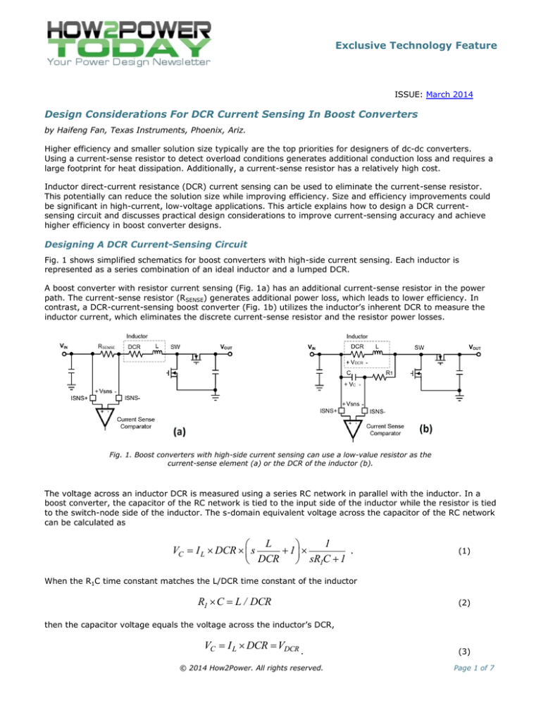
Fig. 1 shows simplified schematics for boost converters with high-side current sensing. Each inductor is
represented as a series combination of an ideal inductor and a lumped DCR.
A boost converter with resistor current sensing (Fig. 1a) has an additional current-sense resistor in the power
path. The current-sense resistor (RSENSE) generates additional power loss, which leads to lower efficiency. In
contrast, a DCR-current-sensing boost converter (Fig. 1b) utilizes the inductor’s inherent DCR to measure the
inductor current, which eliminates the discrete current-sense resistor and the resistor power losses.
Fig. 1. Boost converters with high-side current sensing can use a low-value resistor as the
current-sense element (a) or the DCR of the inductor (b).
The voltage across an inductor DCR is measured using a series RC network in parallel with the inductor. In a
boost converter, the capacitor of the RC network is tied to the input side of the inductor while the resistor is tied
to the switch-node side of the inductor. The s-domain equivalent voltage across the capacitor of the RC network
can be calculated as
L
1
VC I L DCR s
1
.
DCR
sR1C 1
(1)
When the R1C time constant matches the L/DCR time constant of the inductor
R1 C L / DCR
(2)
then the capacitor voltage equals the voltage across the inductor’s DCR,
VC I L DCR VDCR
.
© 2014 How2Power. All rights reserved.
(3)
Page 1 of 7
Exclusive Technology Feature
The equivalent current-sense resistance is thus equal to DCR,
Rsns DCR .
(4)
In applications where DCR is higher than the desired current-sense resistance, a resistor divider can be used to
scale the sensed voltage signal. Fig. 2 shows DCR current sensing with a resistor divider, and in this circuit the
s-domain equivalent capacitor voltage becomes
VC I L DCR
R2
L
1
s
1
R
R
R1 R2 DCR
s 1 2 C 1
R1 R2
.
(5)
Fig. 2. DCR current sensing with a resistor divider.
As with the case where no resistor divider was present, by matching the equivalent RC time constant with the
inductor L/DCR time constant in this case yields
R1R2
C L / DCR
R1 R2
(6)
where the capacitor voltage is proportional to the inductor current, inductor DCR, and resistor divider ratio,
VC I L DCR
R2
R1 R2
(7)
and the equivalent current-sense resistance is then equal to
Rsns
R2
DCR .
R1 R2
(8)
Theoretically, by designing the RC network and resistor divider such that the RC time constant matches the
inductor L/DCR time constant, the inductor current can be measured accurately. However, several practical
factors should be taken into account to ensure current-sensing accuracy.
© 2014 How2Power. All rights reserved.
Page 2 of 7
Exclusive Technology Feature
Improving Current-Sensing Accuracy
Parametric variations of the inductance L, DCR, and the RC time constant cause mismatching and affect
current-sensing accuracy. Besides the time constant-mismatching, the current-sense comparator also has an
impact on current-sensing accuracy.
A practical high-side current-sense comparator of a boost converter usually has bias currents (IBN and IBP in Fig.
3) flowing into the inputs. The bias current of the current-sense comparator’s inverting input flows through
resistor R1, generating an offset voltage, which results in an error between V C and VDCR (Fig. 4), even if the RC
time constant and inductor L/DCR time constant match. This error could be significant compared to a small
current-sense signal, especially if the amplifier bias current and R1 are relatively large.
For example, TI’s TPS43061 synchronous boost controller has a typical sense-comparator bias current of 70 µA.
For a 1-kΩ resistor, R1, the sense error is
Verror R1 I BN 70mV
.
(9)
Fig. 3. DCR current sensing with offset voltage cancellation without a resistor divider (a) or with a
resistor divider (b).
Fig. 4. Current-sense error caused by the bias current.
This error is of the same order as the current-limit threshold (73 mV), and is therefore unacceptable. This error
can be reduced by choosing a smaller R1. However, a small R1 consumes more power and reduces efficiency,
especially under light-load conditions.
© 2014 How2Power. All rights reserved.
Page 3 of 7
Exclusive Technology Feature
The bias currents to the two inputs of the current-sense comparator are typically almost equal. A resistor (R3 in
Fig. 3) can be placed between the RC network and non-inverting input of the current-sense comparator to
correct the input bias current error. Assuming identical bias currents, R3 should be chosen to be equal to R1 for
DCR current sensing without a resistor divider (Fig. 3a).
For DCR current sensing with a resistor divider (Fig. 3b), R3 should be designed to be equal to the equivalent
resistance of R1 and R2 connected in parallel. By cancelling the offset voltage caused by the bias current,
current-sensing accuracy is improved. With balanced resistance at the comparator inputs, relatively high-value
resistors can be used to minimize power loss and improve efficiency.
Power Loss And Efficiency Analysis
Both resistor current sensing and DCR current sensing generate power loss, however their power loss
mechanisms are different. In a resistor sensing scheme, the inductor current flows through a current sense
resistor generating additional power loss in the current-sense resistor. This power loss is related to the inductor
current and current-sense resistance, and is calculated by
PRSENSE I L _ rms 2 RSENSE
.
(10)
Given the inductor current (IL_rms), the power loss dissipated in the current-sense resistor can be reduced by
lowering its resistance. However, a current sense-resistance that is too low results in low signal-to-noise ratio
(SNR) and reduced noise immunity. Furthermore, the current-sense resistance must be chosen to set the
desired current-limit threshold.
In a DCR sensing configuration, the inductor voltage is applied to the RC network, producing power loss in the
resistor (R1). The voltage across the resistor is approximately equal to the inductor voltage since the voltage
across the capacitor is small and usually negligible. Fig. 5 (parts a and b) show ideal waveforms for the voltage
across R1 for the converter operating in continuous-conduction mode (CCM) and discontinuous-conduction mode
(DCM), respectively.
Fig. 5 The voltage across R1 with the boost converter operating in continuous conduction mode
(a) and discontinuous conduction mode (b).
In CCM, the power loss dissipated in R1 is expressed as
V VIN 1 D
V 2
PR1 IN D OUT
R1
R1
2
© 2014 How2Power. All rights reserved.
(11)
Page 4 of 7
Exclusive Technology Feature
where D is the duty cycle of the boost converter.
This power loss is determined by the inductor voltage (input voltage, output voltage and duty cycle) and the
resistance of R1. Lower voltage generates reduced current-sensing power loss in the DCR sensing circuit. This
power loss also can be reduced by increasing R1. In CCM, this power loss is independent of inductor current. In
DCM, the load current has an effect on duty cycle, and therefore on power loss. The smaller the load current in
DCM, the lower the power loss.
Fig. 6 shows an analytical comparison of the current-sensing power loss using resistor sensing and DCR sensing
in CCM. DCR sensing usually reduces current-sensing power loss and improves efficiency under heavy load
conditions, while resistor sensing has higher efficiency at very light load conditions. DCR sensing also provides
substantial benefits in low-voltage high-current applications.
Fig. 6. A comparison of current-sensing power loss for resistor versus inductor DCR sensing.
In Fig. 7, one boost converter using DCR sensing is built and tested to compare with another using resistor
sensing. Key parameters of the two boost converters are shown in the table. Both converters use TI’s TPS43061
synchronous boost controller and a 3.3-µH inductor with 9.42-mΩ DCR.
Table 1. A comparison of key parameters for boost converters using resistor versus DCR sensing.
RSENSE (mΩ)
R1 (kΩ)
C (µF)
R3 (kΩ)
Resistor
sensing
10
N/A
N/A
N/A
DCR sensing
N/A
1.18
0.33
1.18
DCR (mΩ)
L (µH)
9.42
3.3
Fig. 7 shows the boost converter with DCR current sensing wherein a 1.18-kΩ resistor is used for both R1 and
R3, and a 0.33-µF capacitor is used for the capacitor in the RC network. In the version of this boost converter
© 2014 How2Power. All rights reserved.
Page 5 of 7
Exclusive Technology Feature
with resistor sensing, a 10-mΩ discrete resistor is inserted into the circuit (just before the inductor) as the
sense element.
Fig. 7. Boost converter using a synchronous boost controller with DCR current sensing.
These two boost converters are evaluated while boosting the 6-V input voltage to 15-V output with 2-A rated
output current. Fig. 8 shows the measured efficiency. DCR sensing improves efficiency under high outputcurrent conditions, but does not outperform resistor sensing at low current levels.
Fig. 8. Efficiency comparison between DCR sensing and resistor sensing.
© 2014 How2Power. All rights reserved.
Page 6 of 7
Exclusive Technology Feature
Conclusion
Inductor DCR current sensing eliminates the relatively high cost and large footprint of discrete current-sense
resistors. In addition to matching the RC time constant with the L/DCR time constant of the inductor, the offset
voltage introduced by input bias currents of a practical current-sense comparator should be addressed to
ensure accurate current sensing. DCR sensing can provide substantial efficiency improvement in low-voltage
high-current applications.
Reference
“Low Quiescent Current Synchronous Boost DC/DC Controller with Wide VIN Range,” TPS43060/61 Datasheet
(SLVSBP4), Texas Instruments, September 2013.
About The Author
Haifeng Fan is a systems engineer with Texas Instruments’ Power Products Business
Group where he is responsible for new product definition, systems modeling and
simulation, evaluation module (EVM) designs, new product promotion, and customer
technical support. Haifeng received his Ph.D. in electrical engineering from Florida
State University, Tallahassee, Florida; his MSEE from Zhejiang University, Hangzhou,
China, and his BSEE from Huazhong University of Science and Technology, Wuhan,
China. Haifeng can be reached at ti_haifengfan@list.ti.com.
For further reading on the design of current sensing circuitry, see the How2Power Design Guide, select the
Advanced Search option, go to Search by Design Guide Category and select “Test and Measurement” in the
Design Area category.
© 2014 How2Power. All rights reserved.
Page 7 of 7


