70.4: Optical Characterization of Scattering Anti
advertisement

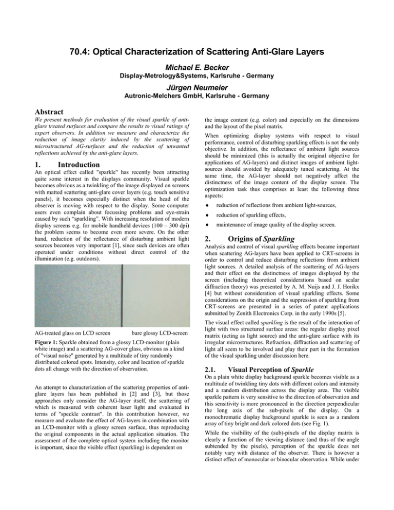
70.4: Optical Characterization of Scattering Anti-Glare Layers Michael E. Becker Display-Metrology&Systems, Karlsruhe - Germany Jürgen Neumeier Autronic-Melchers GmbH, Karlsruhe - Germany Abstract We present methods for evaluation of the visual sparkle of antiglare treated surfaces and compare the results to visual ratings of expert observers. In addition we measure and characterize the reduction of image clarity induced by the scattering of microstructured AG-surfaces and the reduction of unwanted reflections achieved by the anti-glare layers. 1. Introduction An optical effect called "sparkle" has recently been attracting quite some interest in the displays community. Visual sparkle becomes obvious as a twinkling of the image displayed on screens with matted scattering anti-glare cover layers (e.g. touch sensitive panels), it becomes especially distinct when the head of the observer is moving with respect to the display. Some computer users even complain about focussing problems and eye-strain caused by such “sparkling”. With increasing resolution of modern display screens e.g. for mobile handheld devices (100 – 300 dpi) the problem seems to become even more severe. On the other hand, reduction of the reflectance of disturbing ambient light sources becomes very important [1], since such devices are often operated under conditions without direct control of the illumination (e.g. outdoors). AG-treated glass on LCD screen bare glossy LCD-screen Figure 1: Sparkle obtained from a glossy LCD-monitor (plain white image) and a scattering AG-cover glass, obvious as a kind of "visual noise" generated by a multitude of tiny randomly distributed colored spots. Intensity, color and location of sparkle dots all change with the direction of observation. An attempt to characterization of the scattering properties of antiglare layers has been published in [2] and [3], but those approaches only consider the AG-layer itself, the scattering of which is measured with coherent laser light and evaluated in terms of "speckle contrast". In this contribution however, we measure and evaluate the effect of AG-layers in combination with an LCD-monitor with a glossy screen surface, thus reproducing the original components in the actual application situation. The assessment of the complete optical system including the monitor is important, since the visible effect (sparkling) is dependent on the image content (e.g. color) and especially on the dimensions and the layout of the pixel matrix. When optimizing display systems with respect to visual performance, control of disturbing sparkling effects is not the only objective. In addition, the reflectance of ambient light sources should be minimized (this is actually the original objective for applications of AG-layers) and distinct images of ambient lightsources should avoided by adequately tuned scattering. At the same time, the AG-layer should not negatively affect the distinctness of the image content of the display screen. The optimization task thus comprises at least the following three aspects: ♦ reduction of reflections from ambient light-sources, ♦ reduction of sparkling effects, ♦ maintenance of image quality of the display screen. 2. Origins of Sparkling Analysis and control of visual sparkling effects became important when scattering AG-layers have been applied to CRT-screens in order to control and reduce disturbing reflections from ambient light sources. A detailed analysis of the scattering of AG-layers and their effect on the distinctness of images displayed by the screen (including theoretical considerations based on scalar diffraction theory) was presented by A. M. Nuijs and J. J. Horikx [4] but without consideration of visual sparkling effects. Some considerations on the origin and the suppression of sparkling from CRT-screens are presented in a series of patent applications submitted by Zenith Electronics Corp. in the early 1990s [5]. The visual effect called sparkling is the result of the interaction of light with two structured surface areas: the regular display pixel matrix (acting as light source) and the anti-glare surface with its irregular microstructures. Refraction, diffraction and scattering of light all seem to be involved and play their part in the formation of the visual sparkling under discussion here. 2.1. Visual Perception of Sparkle On a plain white display background sparkle becomes visible as a multitude of twinkling tiny dots with different colors and intensity and a random distribution across the display area. The visible sparkle pattern is very sensitive to the direction of observation and this sensitivity is more pronounced in the direction perpendicular the long axis of the sub-pixels of the display. On a monochromatic display background sparkle is seen as a random array of tiny bright and dark colored dots (see Fig. 1). While the visibility of the (sub)-pixels of the display matrix is clearly a function of the viewing distance (and thus of the angle subtended by the pixels), perception of the sparkle does not notably vary with distance of the observer. There is however a distinct effect of monocular or binocular observation. While under 0.0 / Lead Author binocular observation the sparkling pattern is composed of tiny dots which seem to be most distinct when the eyes are focused behind or in front of the display surface, monocular observation reveals small patches (granules) of varying intensity and color with irregular organic (cell-like) boundaries. When a scattering AG-layer is put over a display screen in a wedge-like manner (i.e. touching the display surface with one edge and about 100 mm away from the display surface at the other side, a staircase pattern of stripes that does not change with direction of observation can be seen under binocular observation only. This visual effect is very close to that of a single image random dot stereogram introduced by Tyler in 1979 [6]. 3.1. Difference Method A first image is recorded and then the AG-glass is slightly shifted laterally before a second image is recorded. Evaluation of the sparkling is done by subtracting one image from the other. Sparkling becomes obvious in the part of the image with the shifted AG-layer, the rest of the image must remain uniform as shown in Fig. 2b. The amount of sparkling is evaluated by dividing the standard deviation of gray-levels of a selected region in the sparkling area by the mean gray-value of the same region of one of the original images. The visual experience of sparkle is quite similar to that of speckle obtained by interference of a multitude of monochromatic waves. The 3-dimensional speckle pattern exhibits a strong variation with the conditions of observation (location of observer, direction of observation, pupil size, etc.). 3. New Approach for Measurement and Rating of Sparkle Effects In order to best reproduce the actual application situation we use an LCD-monitor with a glossy screen surface as light-source on which the AG-treated glass sheets are placed, depending on the application either in direct contact to the screen surface or with a certain constant air gap. An electronic camera (typically 1300 * 1000 pixels without color filters) records the resulting image with a magnification in the range of 5 - 25 camera pixels per display pixel (i.e. 5 – 7 camera pixel per sub-pixel of the display). The working distance has been chosen between 15 cm and 700 cm in our measurements. The visible sparkling is stimulated by the intensity modulation caused by the sub-pixels of the display screen and it becomes obvious as an additional superimposed intensity modulation across the display screen and thus also the recorded image. The intensity modulation caused by the display pixels remains apparent as a regular matrix of sub-pixels (details of the raster depending on the displayed color) while the sparkle is obvious as a superimposed irregular intensity modulation with a continuous range of spatial frequencies. So a basic problem of sparkle evaluation is to separate the statistic intensity modulations (sparkle) from the regular ones (display pixel matrix). In order to achieve this separation we have investigated two alternative approaches: the difference and the filter method. Figure 3a: Image of AG-layer on top of display surface covering half of the region of interest (left half). The right half is the bare LCD-screen. 3.2. Figure 3b: Regular intensity modulations removed by image spatial filtering. Sparkling becomes obvious in the left half of the image. Spatial Filtering When numerous measurements and evaluations have to be carried out in the context of a screening process it may be advantageous if no mechanical interference (shifting of the AG-layer) is required. So instead of separating the sparkling from the pixel structure by image subtraction we have also explored spatial filtering e.g. with appropriate masking in Fourier space. The amount of sparkling is again evaluated as the standard deviation of a selected area after filtering divided by the mean gray-value of the same area of the original (unfiltered) image. Results of sparkle evaluation The results obtained for a variety of anti-glare treated glass substrates have been compared to the visual rating of expert observers to check the validity of the measurement method. Sparkle evaluation 1.0 image filtering difference 0.9 0.8 measurement 0.7 0.6 0.5 0.4 0.3 0.2 0.1 Figure 2a: Image of AG-layer on top of display surface covering half of the region of interest (left half). The right half is the bare LCD-screen. Figure 2b: Regular intensity modulations removed by image subtraction. Sparkling becomes obvious in the left half of the image. 0.0 0.0 0.2 0.4 0.6 0.8 1.0 visual rating Figure 4: Sparkle values (normalized) from difference and filter method for 14 samples compared to (normalized) visual ratings of expert observers (8 categories). Comparison of the results of our measurements and evaluations to visual ratings shows that the difference method accurately reproduces the ranking sequence of the observers while the filter method, in some cases, still reverses the ranking sequence. 4. Reduction of Disturbing Reflections 60000 50000 40000 30000 20000 10000 0 0 Figure 5a: Image of linear light source reflected in the bare glossy LCD-screen (top) and in an AG-layer (bottom). 50 100 150 200 250 300 350 400 Figure 5a: Profile of light intensity reflected by the bare LCD-screen (red) and by the scattering AG-layer (blue). The subject of the advantages and drawbacks of glossy and matte display screens has raised quite some attention and has been discussed in various publications (see e.g. [1]). In order to assure good reading and working conditions with electronic display screens, reflections from ambient light sources should be reduced in both intensity and distinctness of image (i.e. no distinct image of the light source should be visible in the display screen) in order to avoid glare and fusion conflicts. These objectives can be achieved simultaneously by carefully optimized scattering antiglare layers. The reduction of reflected light intensity and its directional distribution can be evaluated via measurement of e.g. the bidirectional reflectance distribution function (BRDF) of which we have implemented a simplified version in our measuring setup [7]. Both the display screen and the AG-layer on its top in our measuring arrangement are illuminated by a linear light source (CCFL) and the intensity of the reflected light is recorded as a function of the location on the display. From the intensities of light reflected in the mirror direction we obtain the anti-reflection factor, AR, and the shape of the intensity vs. location curve describes the scattering characteristics of the AGlayer as illustrated in figs. 5. The more the intensity of light in the specular (mirror) direction is reduced the more light is scattered into other directions of propagation. 5. Evaluation of Distinctness of Image Distinctness of image, DOI, is a quantification of the deviation of the direction of light propagation from the regular direction by scattering during transmission or reflection. DOI is sensitive to even subtle scattering effects; the more light is being scattered out of the regular direction the more the initially sharp (well defined) image is blurred (that is, small image details are being lost). DOI is measured to characterize the visual appearance of e.g. polished high-gloss surfaces such as automotive car finishes, mirrors, beyond the capabilities of gloss (see ASTM E430-5 [8]). The scattering of the AG-layer has an effect that is similar to a low-pass filter, it affects both the shape of the luminance modulation of the display screen as well as the amplitude as can be seen in Figs. 2a and 3a. The reduction of distinctness of image, is described in this work by a modulation transfer function, MTF, given by the ratio of the amplitudes of transmitted light intensity with and without AG-layer. Figure 7: In-plane bidirectional transmittance distribution function (BTDF) of AG-treated glass with different gloss values (70, 90 and 120). The red curve shows the source-receiver signature of the conoscopic measurement system (FWHM = 0.55°). 60000 50000 40000 30000 20000 10000 0 0 50 100 150 200 250 300 350 400 Figure 6: Directional variations of the intensity of light reflected from the AG-layers used for sparkle evaluation in this article. Figure 8: Modulation of transmitted intensity obtained from Fig. 2a (red: without AG-layer, blue: with AG-layer); the scattering AG-layer reduces the amplitude and attenuates high-frequency components (smoothing). 0.0 / Lead Author Discussion 8. 1.0 Spkl-Visual 1/MTF AR 0.8 0.6 0.4 0.2 spkl-vis MTF AR 0.0000 0.3088 0.10182 GL30 0.1429 0.4708 0.12581 GL60 0.2857 0.6015 0.31639 9. [1] M. E. Becker: Matte vs. glossy displays: A technical 0.2857 0.0189 0.07240 GL75 0.4286 0.7853 0.30988 GL85 0.4286 0.7323 0.37418 GW4 0.5714 0.1303 0.09463 GW125 0.5714 0.9143 0.79860 GW100 0.7143 0.8766 0.70589 GW10 0.8571 0.3312 0.11907 GW80 0.8571 0.8384 0.43105 GW20 1.0000 0.5733 0.17802 GW40 1.0000 0.7124 0.23099 GW60 1.0000 0.7775 0.33958 Table 1: Summary of visual rating of sparkle (spkl-vis), reduction of distinctness of image (MTF) and reduction of unwanted reflections (AR) for 14 sheets of glass with a range of different AG-treatments. GW60 Figure 9: Graphical representation summarizing the properties of 14 AG-layers. The optimum case is given by low sparkle-values, high suppression of reflections (low AR-value) and high MTFvalues (shown here as 1/MTF). GL20 GW1 GW40 GW20 GW80 GW10 GW100 GW125 GW4 GL85 GL75 0.0 GW1 The proposed method for the optical characterization of scattering anti-glare layers can be used by manufacturers of such coatings for optimization of their products, since the suppression of unwanted reflections and the undesirable reduction of distinctness of image are obtained at the same time. Manufacturers of electronic equipment that are combining visual displays with touch sensitive input devices can characterize their products for obtaining suitable results concerning suppression of reflections and maintaining distinctness of image. This metrology method can be a basis for objective rating of the optical properties and thus for unambiguous communication between customer and supplier. GL60 Conclusion AG-layer 1.2 GL30 7. Acknowledgements The authors gratefully acknowledge the support by Dr. Reich and Mr. Schaude from Berliner Glas Surface Technology [9], the preparation and provision of AG-treated glass samples together with visual sparkle ratings, and their stimulating interest in the measurement approach. GL20 6. We have introduced two approaches for measurement and evaluation of visual sparkle effects and compared the results to the ranking of visual observations. While the difference method clearly reproduces the ranking of the visual observations, the image filter method in some cases reverses the ranking sequence. More work is required to improve the data processing and thus the match between measurement and visual rating. Further investigations are also scheduled to find out if the distinctions in visual rating categories obtained by the difference method can be confirmed by visual rating. [2] [3] [4] [5] [6] [7] [8] [9] References question or just a matter of personal preferences?, Veritas & Visus Display Standard, September 2008, Vol3, No6/7 D. R. Cairns, P. Evans: Laser Speckle of Textured Surfaces: Towards High Performance Anti-Glare Surfaces, SID'07 Digest, pp. 407-409 D. K. P. Huckaby, D. R. Cairns: Quantifying "Sparkle" of Anti-Glare Surfaces, SID'09 Digest, pp. 511-513 A. M. Nuijs, J. J. L. Horikx: Diffraction and scattering at antiglare structures for display devices, APPLIED OPTICS, 33,18(1994), pp. 4058-4068 e.g. US Patent 4 972 117 B. Julesz: Stereopsis and binocular 3d Stereogram rivalry of contours, JOSA (1963) 53:994–999 M. E. Becker: Display Reflectance: Basics, measurement, and rating, Journal of the SID, November 2006, Volume 14, Issue 11, pp. 1003-1017 ASTM Standards on Color & Appearance Measurement Berliner Glas Surface Technology www.berlinerglas-st.de

