1. Introduction
The purpose of this document is to provide the guidelines to design a low power consumption, low BOM and high
sensitivity CMT2210A Receiver.
2. CMT2210A Schematics Guidelines
The CMT2210A is an ultra low power, high performance, low-cost OOK stand-alone RF receiver for various 300 to
480 MHz wireless applications. The chip is part of the CMOSTEK NextGenRFTM family, which includes a complete
line of transmitters, receivers and transceivers. To give the CMT2210A schematic design guidelines, an example of
315/433.92 MHz application is given below.
2.1 CMT2210A Evaluation Module Schematic
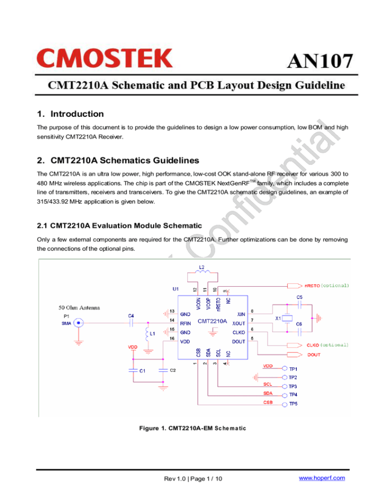
Only a few external components are required for the CMT2210A. Further optimizations can be done by removing
the connections of the optional pins.
Figure 1. CMT2210A-EM Sc he m a tic
Rev 1.0 | Page 1 / 10
www.hoperf.com
AN107
Notes:
1.
L2 is the VCO tank inductor. The VCO oscillates at the frequency which is 2x of the RF frequency. In order to
suppress the spurious emission and minimize phase noise, a high-Q inductor is used. For a 433.92 MHz
design it is suggested to use a 22 nH inductor with Q > 25 at 800 MHz. For a 315 MHz design it is suggested to
use a 33 nH inductor with Q > 25 at 600 MHz.
2.
L1 and C4 transform the impedance seen at the RFIN pin to the antenna impedance.
3.
C1 and C2 are the power supply decoupling capacitors. C1 is an optional decoupling capacitor depending on
the power supply purity level.
4.
The crystal oscillator consists of an extent crystal X1 and two loading capacitors (C5 and C6). The Total load
capacitance seen between the crystal terminals should equal CL for the crystal to oscillate at the specified
frequency.
CL =
C5 * C6 Δ C
+ 2
C5 + C6
The parasitic capacitance ΔC is constituted by pin input capacitance and PCB stray capacitance. The ESR of
the crystal should be within 60 Ω in order to ensure a reliable start-up. The total tolerance is ±20 ppm typically,
which include initial tolerance, crystal loading, aging, and temperature dependence. The acceptable tolerance
depends on RF frequency and channel spacing/bandwidth.
5.
An external clock source can easily be used in place of a crystal oscillator. The incoming clock signal is
recommended to have a peak-to-peak swing in the range of 300 mV to 700 mV and AC-coupled to the XTAL
pin.
6.
P1 is a SMA connector for a 50 Ω antenna.
7.
The DOUT pin outputs the demodulated data.
8.
The test points (TP1/2/3/4/5 connected to VDD, GND, SCL, SDA, and CSB respectively) must be reserved if
EEPROM programming is required. The CSB, SDA and SCL should be left un-connected if they are not used.
9.
By default, an active low reset signal is generated by the internal POR and output via the nRSTO pin. It can be
used to reset the external MCU if it is required. The CMT 2210A can provide a configurable system clock output
from the CLKO pin to drive the external device. The nRSTO and CLKO should be left un-connected if they are
not used.
10. Pin descriptions of the CMT2210A, and the BOM for CMT2210A application are shown in Table 1 and Table 2.
Rev 1.0 | Page 2 / 10
www.hoperf.com
AN107
Table 1. CMT2210A Pin Descriptions
Pin Number
Name
I/O
Descriptions
1
CSB
I
2
SDA
IO
3
SCL
I
3-wire SPI clock input for EEPROM programming
4,9
NC
-
Not connected, leave floating
5
DOUT
O
Received data output
6
CLKO
O
Programmable clock output to drive an external MCU
7
XOUT
O
Crystal oscillator output
8
XIN
I
10
nRSTO
O
Active-low power-on-reset output to reset an external MCU
11
VCOP
IO
VCO tank, connected to an external inductor
12
VCON
13, 15
GND
I
Ground
14
RFIN
I
RF input
16
VDD
I
Power supply input
3-wire SPI chip select input for EEPROM programming
3-wire SPI data input and output for EEPROM programming
Crystal oscillator input or external reference clock input
Table 2. BOM of CMT2210A-EM Application
Designator
Value
Descriptions
315 MHz
U1
CMT2210A 300-480MHz OOK receiver
L1
±5%,0603 multi-layer chip inductor
39
L2
±5%,0603 multi-layer chip inductor
C4
±0.25 pF, 0402 NP0, 50 V
C1
±5%, 0402 NP0, 50 V, optional
C2
C5, C6
X1
Unit
Manufacturer
433.92 MHz
-
-
CMOSTEK
27
nH
Murata LQG18
33
22
nH
Murata LQG18
4.3
3.3
pF
Murata GRM15
470
pF
Murata GRM15
±20%, 0402 X7R, 25 V
0.1
uF
Murata GRM15
±5%, 0402 NP0, 50 V
15
pF
Murata GRM15
±20 ppm, SMD32*25 mm crystal
26
MHz
EPSON
Rev 1.0 | Page 3 / 10
www.hoperf.com
AN107
3. CMT2210A PCB Layout Recommendations
The following PCB layout design guidelines take the CMT2210A-EM as an example.
CMT2210A-EM is a 2-layer PCB using FR4 PCB material. The thickness of the PCB is 0.8 mm; the thickness for
the copper is 1 ounce (0.0356mm); the separation between ground pour copper and traces/pads is 0.3 mm; the
dielectric constant (Er) for the FR4 material is 4.4. In general, the impedance of the coplanar transmission line is in
proportion to the thickness of the PCB and the distance between the routing and grounding around it. It is in inverse
proportion to the width/thickness of the routing and the dielectric constant (Er). Using a conventional transmission
line calculator (such as Txline), a 1-mm width of the 50 Ω coplanar transmission line can be obtained.
3.1 CMT2210A-EM PCB Layout
The PCB layout as shown in Figure 2 has six sections. They are RF Input, Power Supply Decoupling, XTAL Circuit,
VCO Tank Circuit, Digital Signals Routing, and Grounding.
RF Input
Power Supply
Decoupling
VCO Tank
XTA L
Ground ing
Routing Digital
Signals
Figure 2. CMT2210A-EM PCB Layout
Rev 1.0 | Page 4 / 10
www.hoperf.com
AN107
3.1.1 RF Input
Figure 3. RF Inp u t
The RF input section is shown in Figure 3.
1.
Keep the RF signal routing as straight as possible to minimize the loss of the RF signal power.
2.
Place the L1 and C4 as close to each other as possible, and also keep this matching network section as close
to CMT2210A as possible.
3.
The input of the LNA can be modeled as a shunt resistor RLNA (340 Ω) in parallel with a shunt capacitor CLNA
(2.8 pF). A 0.2-mm width transmission line between the L1 and the CMT2210A is used. The width of the
transmission line is 1 mm between L1 and the SMA connector which is of 50 Ω impedance.
4.
It is suggested not to place any silk print on any RF component, as the silk print might impact the dielectric
constant (Er) of the PCB.
5.
The ground pour flooding and the RF signal routing should be smooth to avoid the impedance variation on the
transmission lines, which will result in RF signal reflection and performance inconsistency in mass production.
Wherever possible the bottom (copper) side of the board should allow for a solid ground plane under the RF.
6.
P1 is a SMA connector for the antenna. The monopole antenna is a very popular antenna which most
commonly refers to a quarter-wavelength (λ/4). One antenna element is one λ/4 wavelength and the GND
plane acts as the other λ/4 wavelength which produces an effective λ/2 antenna. Therefore, for monopole
antenna designs the performance of the antenna depends on the ground size. Considering cost, performance
and time-to-market, the user can choose different types of monopole antenna, including PCB antenna, chip
antenna, whip antenna or wire antenna. CMT2210A-EM uses a whip antenna for optimal RF performance.
3.1.2 Power Supply Decoupling
1. Place C1 and C2 as close to the power supply of CMT2110A as possible, as shown in the figure below.
Rev 1.0 | Page 5 / 10
www.hoperf.com
AN107
Figure 4.Power Supply Decoupling Lay o u t
3.1.3 XTAL
Place the crystal as close as possible to the XTAL pin and keep the routing as short as possible in order to reduce
any frequency offsets that may occur. Avoid routing digital signals with sharp edges close to XIN PCB track or
underneath the crystal X1 pad, as this may shift the crystal DC operating point and result in duty-cycle variation.
The XTAL circuit is shown in the figure below.
Figure 5.XTAL Circuit La y o ut
3.1.4 Digital Signals Routing
The digital signals must be routed away from the RF, the XTAL and the VCO circuit to avoid high frequency
harmonics coupling to those sensitive signals. The solid ground should be placed among the SDA, CSB and SCL
signal routings to avoid cross-coupling if possible. R2 is a resistor for internal use only. The user does not need to
include it in the design.
Rev 1.0 | Page 6 / 10
www.hoperf.com
AN107
Figure 6.Digital Signals Ro uti n g
3.1.5 VCO Tank
As the VCO tank inductor L2 is connected to a differential input, the PCB layout should endeavor to respect the
symmetry of this port. To minimize the radiation from the VCO circuit and maintain the high Q factor of the VCO tank,
L2 should be placed as close as possible to the CMT2210A. The VCO tank is surrounded by a solid ground plane.
This ground trace along with the ground vias minimizes the radiation from the VCO, and suppresses the noise
injected into the VCO tank. See figure below for the VCO tank layout.
Figure 7. VCO Tank Lay o ut
Rev 1.0 | Page 7 / 10
www.hoperf.com
AN107
3.1.6 Grounding
1.
Use as much continuous ground plane metallization as possible.
2.
Place a series of ground vias along the PCB edges if possible. The maximum distance between the vias
should be less than λ/10. This is required to reduce the PCB radiation at higher harmonics caused by the
fringing field of routing edges.
Rev 1.0 | Page 8 / 10
www.hoperf.com
AN107
4. Document Change List
Table 3. Document Change List
Rev. No
Chapter
0.9
1.0
-
Description of Changes
Date
Initial released version
2014-06-14
-
2014-06-30
Rev 1.0 | Page 9 / 10
www.hoperf.com
AN107
5. Contact Information
HOPE MICROEL ECTRONICS CO.,LTD
Add: 2/F, Building 3, Pingshan Private Enterprise
Science and Technology Park, Lishan Road, XiLi Town, Nanshan
District, Shenzhen, Guangdong, China
Tel: 86-755-82973805
Fax: 86-755-82973550
Email: sales@hoperf.com
Website: http://www.hoperf.com
http://www.hoperf.cn
HOPE MICROEL ECTRONICS CO.,LTD
Add: 2/F, Building 3, Pingshan Private
Enterprise Science and Technology
Park, Lishan Road, XiLi Town, Nanshan
District, Shenzhen, Guangdong, China
Tel: 86-755-82973805
Fax: 86-755-82973550
Email: sales@hoperf.com
Website: http://www.hoperf.com
http://www.hoperf.cn
This document may contain preliminary information and is subject to
change by Hope Microelectronic s w ithout notice. Hope Microelectronics
assumes no responsibility or liability for any use of the information
contained herein. Nothing in this document shall operate as an express or
implied license or indemnity under the intellectual property rights of Hope
Microelectronics or third parties. The products described in this document
are not intended for use in implantation or other direct life support
applications where malfunction may result in the direct physic al harm or
injury to persons. NO WARRANTIES OF ANY KIND, INCLUDING, BUT
NOT LIMITED TO, THE IMPLIED WARRANTIES OF MECHANTABILITY
OR FITNESS FOR A ARTICULAR PURPOSE, ARE OFFERED IN THIS
DOCUMENT.
©2006, HOPE MICROELECTRONICS CO.,LTD. All rights reserved.
Rev 1.0 | Page 10 / 10
www.hoperf.com

