Exergy Balances and Entropy Generation Rates as the
advertisement
A
R
C
H
I
V
E
S
O
F
M
E
T A
L
L
Volume 58
U
R
G
Y
A
N
D
M
A T
E
R
I
2013
A
L
S
Issue 3
DOI: 10.2478/amm-2013-0054
A. HOŁDA∗ , Z. KOLENDA∗
EXERGY BALANCES AND ENTROPY GENERATION RATES AS THE MATHEMATICAL MODELS FALSIFICATION METHOD
APPLIED FOR ALUMINIUM ELECTROLYSIS PROCESSES
FALSYFIKACJA MODELI MATEMATYCZNYCH NA PODSTAWIE INTENSYWNOŚCI ŹRÓDEŁ ENTROPII NA PRZYKŁADZIE
PROCESU ELEKTROLIZY ALUMINIUM
A new method of falsification of the mathematical model of the processes taking place inside the aluminium electrolysis
cell has been proposed. The method is based on the comparison of the calculation results of the entropy generation rates
obtained in theoretical way with the exergy losses estimated from global exergy balance equation. Following irreversible
processes have been analyzed – electric current flow, diffusion at the cathode, heat and electric current flow through the anode
and cathode, irreversible carbon combustion, heat transfer from electrolyser to the surroundings and convection inside the
electrolyte. Exergy balance calculations have been based on the experimental results from industry. The proposed procedure
shows good accuracy between mathematical model and experimental data.
Keywords: energy, entropy generation rate, mathematical modeling
W artykule zaproponowano metodę falsyfikacji modelu matematycznego procesów jednostkowych zachodzących w elektrolizerze aluminium poprzez porównanie wartości sumarycznego źródła entropii z wartością strat egzergii wynikającą z zamknięcia globalnego bilansu egzergii. Wiarygodność porównania uściślono poprzez uzgodnienie bilansów substancji i energii.
Wyniki obliczeń oparto na bezpośrednich pomiarach przemysłowych. Stwierdzono dobrą zgodność modelu matematycznego z
wynikami pomiarów.
1. Introduction
Falsification of the mathematical models of physical and
chemical processes play important rule in model acceptation
procedure. Falsification methods can be different but their
mathematical independence to the experimental data is necessary. In this paper statistical agreement between entropy generation rates calculated on the basis of thermodynamics of
irreversible processes and independently calculated rates from
global exergy balance equation has been proposed as the general comparison criterion. To improve accuracy of measurement results, the method of adjustment of chemical elements
mass balances has been adopted. Such a procedure allowed to
estimate a posteriori errors of the measurement data.
2. Description of the process
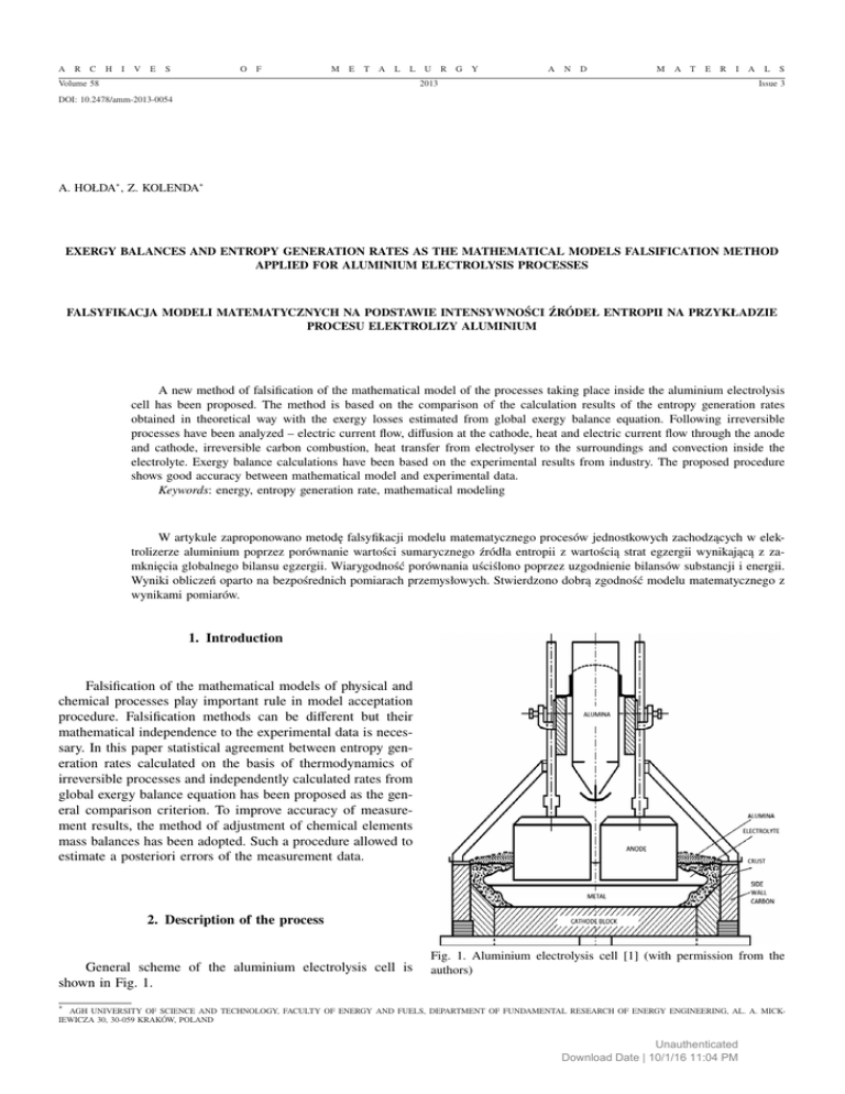
General scheme of the aluminium electrolysis cell is
shown in Fig. 1.
Fig. 1. Aluminium electrolysis cell [1] (with permission from the
authors)
∗
AGH UNIVERSITY OF SCIENCE AND TECHNOLOGY, FACULTY OF ENERGY AND FUELS, DEPARTMENT OF FUNDAMENTAL RESEARCH OF ENERGY ENGINEERING, AL. A. MICKIEWICZA 30, 30-059 KRAKÓW, POLAND
Unauthenticated
Download Date | 10/1/16 11:04 PM
678
Most important driving chemical reaction taking place
inside liquid criolite Na3 AlF6 (l) is
4Al2 O3 (s) + 6C → 8Al(l) + 6CO2 (g)
(1)
Carbon dioxide escapes from the melt and is collected at the
top of the cell. Additionally because the carbon anode is in
contact with atmospheric air, carbon monoxide CO is formed
according to reaction
2C(s) + O2 (g) → 2CO(g)
(2)
and CO(g) is also collected at the top of the cell. Pure aluminium is formed in the bottom of the cell. The cathode is the
metal layer on the top of the carbon blocks. The liquid product
is collected at regular intervals. The electrolyte is contained on
the top of the liquid aluminium. The anode and cathode consist
of several carbon blocks and conduct electric current from the
liquid aluminium. Electrolyser is insulated in the bottom and
on the sides. The electrolyte and liquid aluminium temperature
is about 960◦ C. The cell electric potential is about 4.2 V and
anode-catode distance is 4.50 cm. Cathodic current density is
about 4.6·103 A/m2 to secure average aluminium production
of 75 kg Al per hour. Usually, aluminium electrolysis cell operates between 100 to 300 kA. Joule heat is transferred through
cell external refractories to the surroundings. The heat losses
are almost 6.5 kWh/kg Al at current efficiency of 0.95. In our
case electric potential of the cell was 4.1 V, current density
4.5 A/m2, aluminium production 73.3 kgAl/h and estimated
heat losses
Q̇o = 6.5kW h/kg Al
(3)
Electric energy was continuously measured and equal
Ẇel = I∆Φ = 12.9 kWh/kg Al
(4)
(5)
Thus, thermodynamic efficiency is
ηth =
Ẇel.min
Ẇel
5.4
=
= 0.42
12.9
(6)
The difference δB = Wel −Wel,min is unavoidable exergy (available energy) losses due to the irreversibilities of the processes
taking place in the electrolyzer. Entropy generation rate can
be calculated from expression
δ Ḃ Ẇel − Ẇel,min
=
To
To
(7)
7.5
= 0.025kW h/kg Al · K
300
(8)
Ṡgen =
and is equal
Ṡgen =
where δ Ḃ represents exergy losses of the process.
The result of any real irreversible process occurs in the
form of exergy (available energy) losses. They are usually calculated on the basis of entropy generation rate from expression
[4]
Wlost = δ Ḃ = T o Ṡgen
(9)
where Ẇlost , δ Ḃ are lost work and energy losses respectively, T o is surroundings temperature and Ṡgen represent entropy
generation rate.
All estimations of the lost work of elementary processes
have been taken directly from the book of Kjelstrup and Bedeaux [1] (with permission from the authors). The following
numerical data have been used in calculation:
I = 230 kA – electric current,
∆ΦI = -1.7 V – potential drop across the electrolyte,
T o = 300 K – surroundings temperature,
T c = 960 o C – molten electrolyte temperature,
∆x = 1 mm – thickness of diffusion layer at the cathode
surface,
κ = 19.0 kΩm−1 – electric conductivity of the cathode
diffusion layer,
A = 50 m2 – surface area of the cathode.
The work losses are:
– Lost work due to charge transfer
– The bulk electrolyte
Wlost,1 =
To
(−I∆Φl ) = 1.3 kWh/kg Al
Tc
Ṡgen,1 = 4.33 · 10−3 kW h/K · kg Al
(10)
(11)
It mainly describes ohmic losses through the electrolyte layer
– The diffusion layer at the cathode
Wlost,2 =
To I 2
∆x = 0.05 kWh/kg Al
Tc κ A
Ṡgen,2 = 0.17 · 10−3 kW h/K · kg Al
From theory of electrolysis process
Ẇel,min = I∆Φmin = 5.4 kWh/kg Al
3. Theoretical estimation of exergy losses
(12)
(13)
It represent entropy generation due to the chemical potential
gradient of the ions Na+ and Al3+ at the layer close to the
cathode surface and electric potential drop.
– The electrode surfaces
Wlost,3 = 0.48kW h/kg Al
(14)
Sgen,3 = 1.60 · 10−3 kW h/K · kg Al
(15)
It describes entropy generation rates of several elementary
processes occurring at the electrode surfaces estimated by the
electrode overpotential (˜0.50 V). The above value represents
processes at the anode surface as at the cathode surface value
of Ṡgen is negligible.
– The carbon electrodes
It results from the simultaneous heat and electric current
flows through the carbon parts of the anode and cathode, According to the thermodynamics of irreversible processes
!
I 1
+
−∆Φ j
(16)
Ṡgen = q̇ j · ∇
Tj
T
( j = 1,2 and denotes anode and cathode blocks, respectively.)
where
– heat flow
Unauthenticated
Download Date | 10/1/16 11:04 PM
679
∆T
I
+ πj
∆x
F
π j ∆T ∆x
∆Φ j = −
−
I
T ∆x
κj
q̇ j = −k j A j
(17)
– Radiation and convection
Simplified calculations of the radiative and convective
fluxes lead to the final value
(18)
Wlos,rad = 0.90kW h/kg Al
where π j is Peltier heat.
Introducing Eq. (17) and (18) into Eq. (16)
Ṡgen, j
(26)
−3
Ṡgen,rad = 3.0 · 10 kW h/K · kg Al
(27)
Wlost,con = 2.30kW h/kg Al
(28)
−3
Ṡgen,con = 7.67 · 10 kW h/K · kg Al
!
∆T
1
I 2 ∆x
∇
+
= k j Aj
∆x
Tj
A κ jT
(19)
(29)
– Result of calculation
All contributions are summarize in Table 2.
Data for calculation are given in Table 1.
TABLE 2
The lost work of the cell
TABLE 1
Lost work In the bulk anode and cathode
Loss type
units
Anode
Kathode
Thermal conductivity k j
W/mK
10
13
Temperature interval ∆T
K
Diffusion layer thickness ∆x
m
960-785 960-860
2
Surface area A
m
Electric conductivity κ
−1
−1
Ω m
Charge transfer
Loss location
Amount lost
(kWh/kg Al )
Electrolyte resistant
1.30
Diffusion layer
0.10
Electrode surfaces
0.50
0.35
0.44
Bulk cathode
0.30
30
50
Bulk anode
0.30
19 000
40 000
Hot reactants
Al and CO2
0.30
Peltier heat π
J · kmol
−1
1520
2446
Chemical reaction
Anode
0.10
Work losses W lost
kWh/kg Al
0.33
0.33
Thermal
Wall, surroundings
4.80
Σ
7.70
– Lost work by excess carbon consumption
Wlost,r = 0.1kW h/kg Al
(20)
This value is usually estimated from the carbon consumption
which average value is 0.35 to 0.4 kgC/kgAl. From entropy
change calculation of the reaction (2C(s) + Q2(g) → 2CO(g) )
and Gibbs free enthalpy change equal to -219.5 kJ/molCO .
Ṡgen = 0.33 · 10−3 kW h/K · kg Al
(21)
– Lost work due to heat transfer through the walls of container
!
1
1
Wlost = T o Q̇o
−
= 4.8kW h/kg Al
(22)
To Tc
Entropy generation rate for the cell is equal
P
Wlost
7.70
Ṡgen =
=
= 2.57 · 10−2 kW h/K · kg Al
To
300
(30)
4. Entropy generation rate calculation from exergy
balance equation
General scheme of the system for exergy analysis purposes is shown in Fig. 2.
It is equal to the Carnot-cycle efficiency where Q̇o = 6.50
kWh/kg Al . is total heat transferred to the surroundings.
– Conduction across the wall material
!
∆T j
1
Aj∆
(23)
Wlost, j = −k j T o
∆x j
Tj
Where j denotes different walls of the electrolyser (top, sides
and bottom), ∆T j is temperature difference between boundary
surfaces, ∆x j is thickness of the wall and ∇(1/T ) describes
temperature gradient along wall thickness. Details and results
of calculation can be found in [1]. Finally, the lost work is
and
Wlost = 1.6kW h/kg Al
(24)
Fig. 2. System under consideration
Ṡgen = 5.33 · 10−3 kW h/K · kg Al
(25)
Assuming steady-state conditions, the exergy balance
equation takes the following form
ḂAl2 O3 + Ḃcr + ḂAlF3 + Ėel = ḂAl + ḂA + Ḃl + Ḃc f + δ Ḃ (31)
Unauthenticated
Download Date | 10/1/16 11:04 PM
680
Where δ Ḃ denotes global exergy losses as the result of the
irreversibilities inside the system including exergy losses due
to heat transfer to surroundings.
Thus
δB = ḂAl2 O3 + Ḃcr + ḂAlF3 + Ėel − ḂAl − ḂA − Ḃl − Ḃc f − ḂQ0 (32)
Calculation procedure is presented below.
Exergy fluxes
Na3 AlF6
xse
=0
(40)
M Na3 AlF6
M Na3 AlF6
Where ṁi are mass flow rate, Mi – molecular weight of i-th
element or compounds, x – mass fraction, ṅ – mole flow rate
of gasous substances, y – mole fraction.
Measurement results with a priori errors are shown in
Table 3.
3
ṁcr
− 3ṁse
TABLE 3
Ḃi = ṁi bth,i
(33)
where ṁi is mass flow rate of the i−th substrate or product of
the process and bth,i their thermal exergy [2]
bth,i = b ph,i + bch,i
(34)
where b ph,i and bch,i denotes specific physical and chemical
exergy, respectively.
Values of bch,i are tabulated in engineering thermodynamic monographs (for example [2]) and b ph,i are calculated from
equation
#
"
p
T
+ RT ln
b ph = c p (T − T o ) − T o ln
To
po
(35)
where c p is specific heat, T – is temperature of the substance,
P – pressure of the system and T o , Po are temperature and
pressure of surroundings.
Before exergy balance calculation to increase its accuracy the method of adjustment of mass balances of principal
chemical elements of the process has been adopted and applied. General theory the adjustment of the directly measured
variables is describes on Appendix1. [3].
In the case of aluminium electrolysis process the following chemical elements have been assumed to be involved in
adjustment procedure – Al, F, C, O2 , Na. Mass balance equations take the form:
◦
AlF3
Na3 AlF6
ṁ Al2 O3
ṁ AlF3 ṁ Al
ṁcr
xse
xse
= 0
2
+
+
−
−ṁse
+
M Al2 O3 M Na3 AlF6 M AlF3 M Al
M AlF3 M Na3 AlF6
(36)
◦ – balance F
6
◦
M Na3 AlF6
AlF3
Na3 AlF6
3xse
ṁ AlF3
6xse
= 0
+3
− ṁse
+
M AlF3
M AlF3
M Na3 AlF6
◦
◦
– balance Na
Mass
fraction
Temperature
kg/kg Al
–
K
1.889 ± 0.05
0.534 ± 0.02
0.01 ± 0.005
0.039 ± 0.015
1.0
1.0
1.0
1.0
298 ± 5%
298 ± 5%
298 ± 5%
298 ± 5%
1.0
0.049 ± 0.015
0.088 ± 0.030
0.088 ± 0.030
(kmol/kg Al )
1.0
1.0
0.7939
0.2061
1.0
1.0
0.324
0.362
0.311
1223 ± 10%
1223 ± 10%
1223 ± 10%
1223 ± 10%
Substrates
Al 2 O3
Anode carbon
Criolite (Na3 AlF 6 )
AlF 3
Products
Liquid Al
Electrolyte losses
AlF3
Na3 AlF6
Carbon foam
Anode gasses
CO
CO2
N2
Electric
consumption
Heat losses to
surroundings
(calculated)
54180 kJ/kg Al (15.05 ± 1.0 kWh/kg A l)
34514 kJ/kg Al (9.31 ± 1.0 kWh/kg Al )
Calculation results of exergy balance elements are shown
in Table 4.
TABLE 4
Exergy balance a priori and a posteriori (after adjustment of mass
balances)
Exergy kWh/kg Al
(a priori)
(a posteriori)
Al 2 O3
1.05 ± 0.03
1.05 ± 0.03
Anode carbon
5.08 ± 0.76
4.43 ± 0.68
Criolite (Na3 AlF 6 ), AlF 3
0.03± 0.01
0.03 ± 0.007
Electric energy
15.05± 1.0
14.91 ± 0.81
21.21 ± 1.58
20.72 ± 1.12
Liquid Al.
9.27 ± 0.37
9.35 ± 0.36
Electrolyte losses
0.15 ± 0.05
0.15 ± 0.02
Carbon foam
0.15 ± 0.05
0.15 ± 0.02
Substrates
Σ
Products
(38)
Anode gases
– balance O2
!
3 ṁ Al2 O3
1 CO
CO2
+ 0.21ṅ p − ṅ ga yga + yga = 0
2 M Al2O3
2
Mass flow rate
(37)
– balance C
ṁC ṁ pw
CO2
=0
−
− ṅ ga yCO
ga + yga
MC
MC
Substance
Substance
– balance Al.
ṁkr
Measurement results with priori errors
Σ
(39)
2.50 ± 0.50
2.64 ± 0.48
12.07 ± 0.62
12.29 ± 0.60
Thus, from a posteriori exergy balance, exergy losses are
δ Ḃ = 20.72 − 12.29 = 8.43kW h/kg Al
Unauthenticated
Download Date | 10/1/16 11:04 PM
(41)
681
APPENDIX 1
and
Ṡgen
1
8.43
= 0.0281 ± 0.0025kW h/K · kg Al
300
=
Ṡgen
2
7.70
= 0.0257kW h/K · kg Al
300
=
(42)
(43)
Relative difference is
Ṡgen − Ṡgen
2
1 Di f f % =
Ṡgen
(44)
m
where
Ṡgen
m
=
1
2
h
Ṡgen
1
i
+ Ṡgen =
2
1
(0.281 + 0.0257) = 0.0269kW h/K · kg Al
2
(45)
Thus
Because of inevitable measurement error mass balance
equation for the principal chemical elements of the process
are not exactly satisfied. From mathematical point of view, the
system of algebraic balance equation is internally contradicted. To obtain most probable values the orthogonal least square
method is proposed. General consideration are discussed bellow.
Lest no denotes a minimum number of independent variable necessary for unique solution of the mass balance equation and n be a number of given functionally independent
observation. Where n is greater than no , the redundancy of
number of statistical degrees of freedom defines as r = n − no
is said to exist, and adjustment becomes necessary on order
to obtain a unique solution. Les l denote a vector of all experimental results and l̃ be a vector of estimates that satisfies
the balance equation. In general the values of l̃ are different
from l and a difference vector
V = l̃ − l
Di f f % =
0.0281 − 0.0257
= 0.089
0.0269
(8.9%)
(46)
Taking under consideration problem of the accuracy and necessary simplifications of mathematical model of elementary
processes occurring inside the electrolysis cell system, the
difference of the estimation of entropy generation rates can
be accepted.
5. Conclusions
New approach to the falsification of mathematical models
of the electrolysis cell elementary processes Has been proposed, The method is based on the exergy balance equation
which allows estimation of exergy losses and entropy generation rates. Additionally, to improve accuracy of the falsification
procedure the adjustment method of the chemical elements
mass balances has been used.
Acknowledgements
This work was partially supported by Polish Ministry of Science
and Higher Education Grant AGH No. 11.11.210.198.
REFERENCES
[1] S. K j e l s t r u p, D. B e d e a u x D ., Elements of Irreversible Thermodynamics for Engineers, Int. Centre for Applied Thermodynamics, Istanbul 2001.
[2] J. S z a r g u t, D.R. M o r r i s, F.R. Steward, Exergy Analysis of Thermal, Chemical and Metallurgical Processes, Hemisphere Publ. Corp. New York 1988.
[3] J. S z a r g u t, Z. K o l e n d a, Theory of Coordination of
Material and Energy Balances of Chemical Processes in Metallurgy, Arch. Hutnictwa XII, 2, 153-169 (1968).
[4] D. K o n d e p u d i, I. P r o g o g i n e, Modern Thermodynamics, Chapter 16, John Wiley and Sons 1998.
(A1)
which has been termed as either a correction or a residual,
plays an important role in calculation. Due to the redundancy
the number of estimates for l̃ and V is infinite. To calculate te
most probable solution, the least squares principle is commonly used as an additional criterion. The least square principle
requires the condition
!2
n
X
vi
T
−2
f (V) = V M V =
→ minimum
(A2)
µi
i=1
To be satisfied simultaneously with the mass balance equations
where M−2 is the weight matrix of the observations (experimental result). The weight M−2 matrix is square and diagonal
and of order equal to the number of observations.
Les us assume that mass balance equations can be performed by the following system of the algebraic non-linear
equations
fi (l̃, x̃) = 0 (i = 1, ..., J),
(A4)
were vector matrices l̃ and x̃ represent a set of variables the
values of which are estimated a priori by direct measurement
l and a set of unknowns x non-measurement variables.
Introducing experimental results l and approximations of
unknown x the system of equations is replaced by
fi (l, x) = w̃i
(A5)
where l = (l1 , ..., lk ), x = (x1 , ..., xm ) and w̃i represents the
residua of origin system of non-linear equations.
To solve the problem numerically, a linearization procedure is applied using the zero and first order terms of the
Taylor expansion. Defining the estimates (most probable values) as
l̃ = l + V and x̃ = x + Y
(A6)
where V represents unknown corrections to the experimental result l, and Y corrections to the approximations of
non-measured variables x, the system can be written in the
form
fi = (V, Y) = wi
(A7)
And after linearization, in the matrix form
AV + BY = W
Unauthenticated
Download Date | 10/1/16 11:04 PM
(A8)
682
where
∂f
∂l
is a J × k Jacobi matrix of rank equal to J,
A=
(A9)
∂f
B=
∂x
(A10)
is a J ×m Jacobi matrix of rank equal to m, and f = { f1 , ..., f J }T
The least squares procedure can now be formulated as
follows:
minimize
φ(v) = VT M−2 V
(A11)
subject to mass balance equations
AV + BY = W
n
(A12)
n
The variables (V, l̃, l, Y, x̃, x) ∈ E , where E denotes an
n-dimensional Euclidean space (n = m + k).
To solve the problem effectively, the Lagrange multipliers
method can be used, which leads to the system of additional
linear equations
AT K = M−2 V
(A13)
and
BT K = 0
(A14)
where K is the column matrix of Lagrange multipliers. A routine calculations gives finally
Y = G−1 BT F−1 W
(A15)
V = M2 AT F−1 (W − BY)
(A16)
F = AM2 AT
(A17)
G = BT F−1 B
(A18)
where
and
If the accuracy of solution of linearized problem is not sufficient the iterative procedure must be applied. In such case,
to get the solution of an original non-linear problem the values of elements of Jacobi matrices A and B are continuously
corrected at each iteration step. The solution a now be used
to calculate , a posteriori errors of directly measurement variables, unknowns and any function containing model variables.
Using the law of error propagation, the expressions for the
covariance matrices can be derived in the form
and
where
Ml2 = M2 − CAM2
(A19)
h
i−1
M2x = BT F−1 B
(A20)
h
i
C = M − 2AT F−1 E − BG−1 BT F−1
(A21)
and E is the unit diagonal matrix.
Received: 20 March 2012.
Unauthenticated
Download Date | 10/1/16 11:04 PM
