GE
Security
EST Fire & Life Safety
Notification Appliances
Overview
Standard Features
Integrity temporal horns and temporal horn-strobes are specially
designed for use with compatible life safety communication and
control equipment to alert occupants of a life safety event. The
horn emits a piercing low frequency sound that is easily heard
above moderate ambient noise levels. The flash from its strobe can
be noticed from almost any position in the room, corridor, or large
open space.
• UL 1971-listed synchronizing strobe
Integrity strobes synchronize to the latest UL 1971 requirements
when used with an external control module (G1M or SIGA-CC1S).
Integrity’s rugged plastic housing is made from durable and fire
retardant, high impact plastic with a slightly textured surface. Its
ingenious mounting plate firmly holds the device in place with a
single screw. A separate trim plate is not required. Terminals accept
up to #12 AWG (2.5mm²) wire for polarized connections.
Synchronization is important because a small portion of the
population have a condition which may cause them to become
disoriented from multiple random flashes of light. Integrity strobes
minimize this risk.
Strobes are shipped with standard wall mount style “FIRE” lens
markings. Where ceiling orientation, other languages, or different
lens markings are required, GE Security offers optional LKW and
LKC series Lens Marking Kits. These optional lens markings simply
snap on to the strobe. Consult GE Security for availability of special
lens markings.
Integrity horns and horn-strobes are designed for 20 to 31 Vdc
operation and must be connected to signal circuits that output a
constant (not pulsed) voltage. A diode is used to allow full signal
circuit supervision.
• Adjustable Audible Output
Select temporal or continuous tones, and High setting for 98 dBA
output or Low setting for 94 dBA sound output.
• Genesis-compatible
Can be mixed with Genesis signals. All Genesis and Integrity
strobes on the same circuit meet UL 1971 synchronization requirements when used with an external control module.
• Approved for public and private mode applications
UL 1971-listed as signaling devices for the hearing impaired and
UL 1638-listed as protective visual signaling appliances.
• Satisfies ADA code requirements
Integrity strobes provide the “Equivalent Facilitation” allowed
under ADA Accessibility Guidelines. A single strobe in rooms up
to 50 ft x 50 ft satisfy both ADA and NFPA codes.
• Durable red or white Noryl front plate
Ideal for outdoor, industrial or harsh environments.
• Field changeable field markings
Lens language or standard “FIRE” marking is easily changed with
optional LKW and LKC series lens kits.
• Easy Installation
Flush mount to standard North American 4” square or two-gang
box. Integrity’s universal mounting plate allows it to be wired
and then left hanging free for easy inspection and testing before
it is fastened to the electrical box.
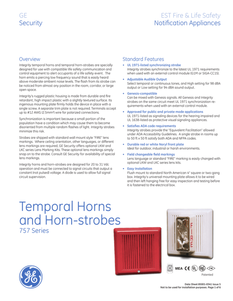
Temporal Horns
and Horn-strobes
757 Series
MEA
Patented
Data Sheet 85001-0341 Issue 5
Not to be used for installation purposes. Page of 6
Horn Application
During installation, the horn is configured for steady or temporal
tone signal and either low (94 dBA) or high (98 dBA) output. When
temporal output is selected all horns on a common two-wire circuit
are self-synchronized (see specifications). External control modules
are not required for audible synchronization.
Suggested sound pressure level for each signaling zone used with
alert or alarm signals is at least 15dB above the average ambient sound level, or 5dB above the maximum sound level having a
duration of at least 60 seconds, whichever is greater, measured 5’
(1.5m) above the floor. The average ambient sound level is the RMS,
A-weighted sound pressure measured over a 24-hour period.
Doubling the distance from the signal to the ear will theoretically result in
a 6 dB reduction of the received sound pressure level. The actual effect
depends on the acoustic properties of materials in the space. A 3 dBA
difference represents a barely noticeable change in volume.
Non-Sleeping Rooms and Corridors: GE Security strobes rated at
less than 110 cd per UL 1971 are intended for use in non-sleeping
areas only. Install with the bottom of the device at least 80 inches
(2.0 m) and no more than 96 inches (2.4 m) above the finished floor.
No point in any space (including corridors) required to have strobes
should be more than 50 feet (15.2 m) from the signal (in the horizontal plane).
Non-Sleeping Rooms
Up to 20’ x 20’ (6.1 x 6.1m)
Up to 30’ x 30’ (9.1 x 9.1m)
Up to 40’ x 40’ (12.2 m x 12.2 m)
Up to 50’ x 50’ (15.2 x 15.2m)
Use One Wall Mounted Model:
One 15 cd strobe
One 30 cd or two 15 cd strobes
One 75 cd or two 30 cd strobes
One 110 cd or two 75 cd strobes
Corridors
Wall Mounted - Model:
15 cd strobes spaced at 100’ (30.5 m)
max. Strobes must be placed within
15’ (4.5m) of each end of the corridor.
Any Length x Max. 20’
(6.1m) Wide
* ADA suggests using 75 cd strobes throughout an area, with spacing that never
exceeds 50 ft from the strobe to any point in the protected space.
Sleeping rooms: GE Security 110 cd strobes are intended for use in
sleeping rooms and should be installed along with a smoke detector. It must be wall mounted at least 80” (2.03 m) above floor level,
but no closer than 24” (610 mm) to the ceiling. The distance from
the strobe to the pillow must not exceed 16’ (4.8 m).
Sleeping Rooms
Any Size
Use One Wall Mounted Model:
110 cd within 16 feet of pillow
Application Notes - USA
Typical Sound Output Distribution
dBA measured at 10 ft in anechoic chamber
757 Series Temporal Horn (‘HIGH’ output)
Strobe Application
GE Security strobes are UL 1971-listed for use indoors as wall-mounted
public-mode notification appliances for the hearing impaired. Prevailing codes require strobes to be used where ambient noise conditions
exceed 105 dBA (87dBA in Canada), where occupants use hearing
protection, and in areas of public accommodation as defined in the
Americans with Disabilities Act (see application notes – USA).
As part of the Enhanced Integrity line of products, 757 Series
strobes exceed UL synchronization requirements (within 10 milliseconds other over a two-hour period) when used with a separatelyinstalled G1M Signal Master or SIGA-CC1S Synchronization Module.
They are fully compatible with Genesis signals.
Combination horn-strobe signals must be installed in accordance
with guidelines established for strobe devices.
Audible signals should never have a sound level less than 75 dBA
at 10’ (3m) per NFPA 72. Signals cannot exceed 120 dBA per ADA
(130 dBA per NFPA 72) at the minimum hearing distance to audible
appliance. Audible signals shall be installed with the top of the device above the floor not less than 90” (2.3m) and below the finished
ceiling at least 6” (150 mm) (per NFPA 72).
Strobes must be used to supplement audible signals wherever the
average ambient sound level exceeds 105 dBA. Combination Audible/Visible signals must be installed per NFPA guidelines established
for strobes.
ADA suggests that the following areas may require Visual Alarm
Signals:
• rest rooms, meeting rooms, and other general usage areas.
•lobbies, hallways, and other common use areas.
•sleeping rooms intended for use by persons with hearing impairment (per Title 1 of ADA).
•work areas used by a person with a hearing impairment (per Title 1 of ADA).
•
The following guidelines are based on ANSI/NFPA 72 National Fire
Alarm Code (1999). When applied and installed in accordance with
that code, GE Security strobes meet or exceed the illumination produced by the ADA-specified 75 candela (cd) strobe at 50 feet.*
Data Sheet 85001-0341 Issue 5
Not to be used for installation purposes. Page of 6
Application Notes - CANADA
Typical Wiring
Based in part on 1995 Canada National Building Code - The fire
alarm signal sound pressure level shall not exceed 110 dBA in any
normally occupied area. The sound pressure level from an audible
signal in a floor area used for occupancies other than residential
occupancies shall be not less than 10 dBA above the ambient noise,
and never less than 65 dBA. The sound pressure level in sleeping
rooms from an audible signal shall not be less than 75 dBA when
any intervening doors between the device and the sleeping room
are closed. Audible signal devices shall be installed not less than 1.8
m to the center of the device above the floor (per CAN/ULC S524).
The strobe must be connected to signal circuits which output a constant (not pulsed) voltage. The horn can be connected to continuous
voltage circuits.
The fire alarm audible signal shall be supplemented by fire alarm
strobes in any floor area where the ambient noise level exceeds
87 dBA, or where the occupants of the floor area use ear protective
devices, are located within an audiometric booth, or are located
within sound insulating enclosures. This also applies to assembly
occupancies in which music and other sounds associated with
performances could exceed 100 dBA.
Strobes shall be installed in a building so that the flash from not
less than one device is visible throughout the floor area or portion thereof in which they are installed. For maximum safety, GE
Security recommends that strobes be installed as per the guidelines
shown here under Strobe Application.
Installation and Mounting
WARNING: These devices will not operate without electrical power. As fires frequently
cause power interruptions, we suggest you discuss further safeguards with your local
fire protection specialist. These visual signal appliances’ flash intensity may not be
adequate to alert or waken occupants in the protected area. Research indicates that
the intensity of strobe needed to awaken 90% of sleeping persons is approximately 100
cd. GE Security recommends that strobes in sleeping rooms be 110 cd minimum.
All models fit to a standard flush mounted, North-American twogang electrical box, 2¾ inch (69 mm) minimum. Optional flush trims
are not required. For surface mount, use GE Security’s custom
indoor and outdoor surface boxes painted in color-matched red or
white epoxy. GE Security recommends that fire alarm horn/strobes
always be installed in accordance with the latest recognized edition
of national and local fire alarm codes.
Data Sheet 85001-0341 Issue 5
Not to be used for installation purposes. Page of 6
Light Output Patterns
45
60
0
50
15
30
45
60
cd
0
50
15
30
45
100
150 90 75
60
'7A' Series Strobe
Horizontal Output
Vertical
-90°
8A Average cd
degrees
-90°
110cd UL min
-30
-45
-60
Vertical
-90°
7Aeg
Average
rees cd
d
-90°
-30
-45
-60
90°
Horizontal
-75
-90
100
90°
Current Draw
Typical Current
110 cd
RMS
Mean
Peak
RMS
Mean
Peak
20 Vdc
121
115
277
248
241
402
24 Vdc
101
96
204
203
197
338
31 Vdc
81
76
173
155
151
280
20 Vfwr
168
97
452
342
202
868
24 Vfwr
146
79
446
286
159
788
UL Rating
110 cd
15/75 cd
RMS
Mean
Peak
RMS
Mean
20 Vdc
113
107
248
228
222
420
24 Vdc
90
85
214
180
175
360
31 Vdc
65
62
174
125
122
280
20 Vfwr
153
81
540
327
177
952
412
260
134
808
24 Vfwr
-15
50
0
cd
7A Average cd
15/75 cd
128
64
0
-15
Peak
15
30
45
60
50
15cd UL min
30
45
60
50
15cd UL min
'7A' Seri
Vertica
-90-75
100
-6
degrees
15
-75
-90
'7A' Series Strobe
100Horizontal
50 Output
cd
90°
'8A' Series Strobe
Horizontal Output
75
90
100
-30
-45
-60
-15
75
-75
90
-90
'8A' Series Strobe
100
Horizontal200
Output 100
-75
-90
200
0
-15
100
cd
8A Average cd
15
15
110cd UL min
100
30
45
60
100
75
90
200
110cd UL min
30
45
60
50
75
90
'7A' Series Strobe
100 Output
200
cd Vertical
8A Average cd
degrees
-30
-45
-60
0
-90-75
50
cd
50
7A Average cd
-60
-45
-30
-15
cd
0
50
15
30
45
15cd UL min
Current Draw Notes and Comments
60
100 90 75
1. Current values are shown in mA.
2. UL Nameplate Rating can vary from Typical Current due to measurement
methods and instruments used.
3. GE Security recommends using the Typical Current for system design
including NAC and Power Supply loading and voltage drop calculations.
4. Use the Vdc RMS current ratings for filtered power supply and battery AH
calculations. Use the Vfwr RMS current ratings for unfiltered power supply
calculations.
5. Fuses, circuit breakers and other overcurrent protection devices are
typically rated for current in RMS values. Most of these devices operate
based upon the heating affect of the current flowing through the device.
The RMS current (not the mean current) determines the heating affect
and therefore, the trip and hold threshold for those devices.
6. Our industry has used ‘mean’ currents over the years. However, UL will
direct the industry to use the 2004 RMS values in the future.
dBA Output
dBA Output Notes and Comments
Horn-strobes
UL464
• All values shown are dBA measured at 10 feet (3.01m).
Peak
High dB
Output
Average
Temporal
Steady
Temporal
Steady
Temporal
Steady
20 Vdc
79.0
82.0
93.5
93.5
100.0
100.0
24 Vdc
79.0
85.0
97.0
97.0
102.0
102.0
Low dB
Output
Temporal
Steady
Temporal
Steady
Temporal
Steady
20 Vdc
75.0
79.0
89.2
89.2
95.4
95.4
24 Vdc
75.0
79.0
93.0
93.0
98.0
98.0
UL464
• UL1480 values measured in reverberation room.
• Average values are measured in anechoic chamber.
Peak
Average
Horns
UL464
Peak
High dB
Output
Temporal
Steady
Temporal
Average
Steady
Temporal
Steady
20 Vdc
79.0
82.0
97.0
97.0
102.5
102.5
24 Vdc
82.0
85.0
98.0
98.0
104.0
104.0
Low dB
Output
Temporal
Steady
Temporal
Steady
Temporal
Steady
20 Vdc
75.0
79.0
92.3
92.3
98.4
98.4
24 Vdc
75.0
82.0
94.0
94.0
99.0
99.0
UL464
Peak
Average
'8A' Ser
Vertica
-90-75
-6
150
100
degrees
100 90 75
15cd UL min
'8A' Series Strobe
Vertical Output
-90-75
-60
150
-45
100
90°
-30
Horizontal
-15
50
degrees
cd
7A Average cd
degrees
75
90
200
'7A' Series Strobe
Vertical Output
-90-75
100
-60
-45
-30
50
-15
Data Sheet 85001-0341 Issue 5
Not to be used for installation purposes. Page of 6
100 90
75
50
60
cd
50
100
150 90 75
6
Specifications
Rated Strobe Output - candela (cd)
UL 1971
UL 1638 & ULC S526
Standalone Synchronization
Characteristics (note 2)
Operating Volts
Horn Output (note 1)
Horn Current
Strobe Flash Synchronization
Compatible Synchronization
Modules
Strobe Marking
Flash Tube Enclosure
Housing
Wire Connections
INDOOR Operating Environment
OUTDOOR Operating Environment
(must use weatherproof box)
Mounting - INDOOR
Mounting - OUTDOOR
Agency Listings
757-1A-T
757-7A-T
757-8A-T
15 cd wall 15 cd ceiling
110 cd wall 60 cd ceiling
N/A (horn only)
75 cd
110 cd
Strobe flash at 1 per second within 200 milliseconds on common circuit Horn pulses at temporal rate
within 200 milliseconds on common circuit
Strobe: 20-24 Vdc Continuous
Horn: 20-31 Vdc Continuous
Anechoic: High Setting - 104 dBA (peak)/98 dBA (avg); Low Setting - 99 dBA (peak)/94 dBA (avg)
Reverberent: High Setting - 85 dBA (continuous)/82 dBA (temporal);
Low Setting - 82 dBA (continuous)/75 dBA (temporal)
High Output: 40 mA @ 24 Vdc; 55mA @ 24 Vrms FWR
Low Output: 20 mA @ 24 Vdc; 28 mA @ 24 Vrms FWR
Synchronized at one flash per second. External control module necessary to meet UL 1971 synchronization
requirements of 10 milliseconds over a two-hour period.
G1M, G1M-RM, SIGA-CC1S, SIGA-MCC1S
Supplied with LKW-1 “FIRE” red letters, vertical both sides (Wall Mount) - see LKW and LKC series for ceiling style
and optional markings.
Clear LEXAN with white marking sleeve
Textured, color impregnated engineered plastics - exceeds 94V-0 UL flammability rating
Terminals - separate, polarized inputs for Horn & Strobe, #12 AWG (2.5mm²) maximum
32-120° F (0-49° C) ambient temperature. 93% relative humidity @ 40° C
98% relative humidity @ 40° C; -35-150° F (-31-66° C) ambient temperature
(757-7A: rated at 17.7 cd @ -35° C per UL/@ -40° C per ULC)
(757-8A: rated at 70.7 cd @ -35° C per UL/@ -40° C per ULC)
Flush: North-American 2-gang box, 3” high x 4” wide x 2¾” (69 mm) minimum
Surface: 757A-SB Back box Bi-directional: 757A-BDF Mounting Frame
Surface: 757A-WB Weatherproof Box
UL 1971, UL 1638, UL 464, ULC S526, ULC S525, MEA, CSFM, FM. CE
(All models comply with ADA Code of Federal Regulation Chapter 28 Part 36 Final Rule)
Note 1 - Measured at 10 ft (3m) @ 24 Vdc. Subtract 3 dBA for models with strobes. Note 2 - Temporal audible pattern is defined as: ½ sec ON, ½ sec OFF, ½ sec ON, ½ sec OFF, ½
sec ON, 1½ sec OFF, then repeat cycle.
Data Sheet 85001-0341 Issue 5
Not to be used for installation purposes. Page of 6
GE
Security
U.S.
T 888-378-2329
F 866-503-3996
Canada
T 519 376 2430
F 519 376 7258
Asia
T 852 2907 8108
F 852 2142 5063
Australia
T 61 3 9259 4700
F 61 3 9259 4799
Europe
T 32 2 725 11 20
F 32 2 721 86 13
Latin America
T 305 593 4301
F 305 593 4300
www.gesecurity.com
© 2006 General Electric Company
All Rights Reserved
Ordering Information
Catalog Number
Description
Temporal Horns
757-1A-T*
Temporal Horn, Red
Ship Wt., lb. (kg)
1.7 (0.8)
Temporal Horn-Strobes
757-7A-T*
Temporal Horn-Strobe, 15/75cd, Red
757-8A-T*
Temporal Horn-Strobe, 110cd, Red
Synchronization Modules
G1M-RM
Genesis Signal Master Remote Mount (1-gang)
SIGA-CC1S
Synchronization Output Module (Standard Mount)
SIGA-MCC1S
Synchronization Output Module (UIO Mount)
Mounting Accessories
757A-SB*
Surface Box, Red, Indoor
757A-WB*
Weatherproof Box, Red, Surface
757A-BDF*
Bi-directional Frame, Red
Lens Marking Kits (see note 1)
LKW-1
“FIRE”, Wall Orientation (supplied)
LKW-1R
“FIRE”, Wall Orientation, RED
LKW-2
“FEU”, Wall Orientation
LKW-3
“FIRE/FEU”, Wall Orientation
LKW-4
“SMOKE”, Wall Orientation
LKW-5
“HALON”, Wall Orientation
LKW-6
“CO2”, Wall Orientation
LKW-7
“EMERGENCY”, Wall Orientation
LKW-8
“ALARM”, Wall Orientation
LKW-9
“FUEGO”, Wall Orientation
2.0 (0.9)
0.2 (0.1)
0.5 (0.23)
0.18 (0.08)
1.5 (0.7)
4 (1.8)
0.1 (.05)
Add Suffix “W” to catalog no. for WHITE. (e.g. 757-7A-TW)
Change “W” to “C” for CEILING mount. (e.g. LKC-1)
Data Sheet 85001-0341 Issue 5
Not to be used for installation purposes. Page of 6

