Mesostructure from Specularity Using Coded Illumination
advertisement

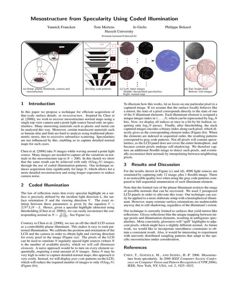
Mesostructure from Specularity Using Coded Illumination Yannick Francken Tom Mertens Jo Gielis Hasselt University Philippe Bekaert firstname.lastname@uhasselt.be 1 1 0 1 0 N V R 1 0 (a) Setup: planar illuminant, camera and mesostructure 1 (b) Gray code patterns Introduction In this paper we propose a technique for efficient acquisition of fine-scale surface details, or mesostructure. Inspired by Chen et al. [2006], we wish to recover mesostructure normal maps using a single top-view camera and a point light source based only on specularities. Many interesting materials such as plastic and metal can be analyzed this way. Moreover, certain translucent materials such as human skin and fruit are hard to analyze using traditional photometric stereo, due to excessive subsurface scattering. Specularities are not influenced by this, enabling us to capture detailed normal maps for such cases. Chen et al. [2006] take N images while waving around a point light source. Many images are needed to capture all the variations in normals in the mesostructure (up to N = 200). In this sketch we show that the same result can be achieved with only O(log2 N) images, through the use of coded illumination patterns. Our technique reduces acquisition time significantly for large N, which allows for a more detailed reconstruction and using longer exposures to reduce camera noise. 2 Coded Illumination The law of reflection states that every specular highlight on a surface is precisely defined by the incident light direction L, the surface orientation N and the viewing direction V . The exact relation between these parameters is given by the equation V = 2(N T L)N − L. Hence, given a specular highlight (detected using thresholding [Chen et al. 2006]), we can easily reconstruct the corresponding normal as N = kVV +L +Lk . See Figure (a). Contrary to Chen et al. [2006], we use an off-the-shelf LCD screen as a controllable planar illuminant. This makes it easy to emit patterned illumination. We calibrate the position and orientation of the LCD and the camera in order to obtain light and viewing direction for every pixel in the image (Figure (a)). The pixels of the LCD can be used to simulate N regularly spaced light sources (where N is the number of available pixels), which we will call illuminant elements. A naive approach would be to turn on every element sequentially, requiring a total amount of N images. Since N may be very high in order to capture detailed normal maps, this approach is very costly. Instead, we will display gray code patterns on the LCD, which will reduce the required number of images to only O(log2 N) (Figure (b)). (c) Left: input images Middle: thresholded specularities Right: normal map (d) Top: height field Bottom: relit images To illustrate how this works, let us focus on one particular pixel in a captured image. If we assume that the surface locally behaves like a mirror, the state of a pixel corresponds directly to the state of one of the N illuminant elements. Each illuminant element is assigned a unique integer index in 1, . . . , N, which can be represented by log2 N bits. Now, we display all indices at once in a bit by bit fashion, requiring only log2 N passes. Finally, after thresholding, the stack captured images encodes a binary index along each pixel, which directly gives us the corresponding element index (Figure (b)). When the elements are indexed in sequential order, the resulting patterns correspond to gray code patterns. Not all pixels will contain specularities, as the LCD panel does not cover the entire hemisphere, and because certain pixels undergo self-shadowing. We therefore capture an additional floodlit image to detect such pixels, and eventually reconstruct their normals by interpolating between neighboring pixels. 3 Results and Discussion For the results shown in Figure (c) and (d), 4096 light sources are simulated by capturing only 12 image, plus 1 floodlit image. There is no noticeable quality loss when using the gray code patterns compared to full sequential enumeration of each illuminant element. Note that the limited size of the planar illuminant restricts the range of possible normals that can be recovered. We used 2 juxtaposed LCD panels in order to alleviate this issue. Our technique can easily be applied to a more elaborate setup with a hemispherical illuminant. However, many extreme surface orientations are undetectable anyway due to self-shadowing, regardless of the illuminant’s extent. Our technique is currently limited to surfaces that yield mirror-like reflections. Glossy reflections blur the unique mapping between image pixels and illumination elements, resulting in ambiguous specularities. More concretely, glossiness will “spill” highlights to adjacent pixels, which might have a slightly different normal. As future work, we would like to incorporate smoothness constraints to obtain a consistent result. Also, it would be interesting to experiment with unevenly distributed sampling patterns that adapt to the specific mesostructure under consideration. References C HEN , T., G OESELE , M., AND S EIDEL , H.-P. 2006. Mesostructure from specularity. In 2006 IEEE Computer Society Conference on Computer Vision and Pattern Recognition (CVPR 2006), IEEE, New York, NY, USA, vol. 2, 1825–1832.


