63249-420-386A1
12/2012
Instruction Bulletin
180 Degree Ceiling Mounted Occupancy Sensors
PS-CDS800 and PS-CUS800
INTRODUCTION
The 180 Degree Ceiling Mount Occupancy Sensors are ideal for use in business and
office settings to accurately detect occupancy and automatically control lighting. The
ceiling-mount design of these low-profile sensors allows the greatest possible motion
sensitivity. An adjustment panel is conveniently located on the front of the sensor,
providing ready access to setting controls after the sensor is installed.
There are two models of 180 Degree Ceiling Mount Occupancy Sensors (See figure on
left):
A. 180 Degree Ultrasonic (US) sensor (PS-CDS800 )
B. 180 Degree Dual Technology Sensor - Passive Infrared (PIR) and Ultrasonic
combined (PS CUS800)
Contents of the Box
FEATURES
Item
Qty
Sensor
Mounting adapter plate
Threaded mounting post
Washer
Lock nut
Mounting screws
Masking strips, sheet*
1
1
1
1
1
2
1
* = Supplied with Dual sensors only.
Description
Ultrasonic
Dual
Coverage area
1000 sq. ft.
1000 sq. ft.
Field of view
0.5-250 foot candles
Adjustable time delay
15 sec.-30 min.
Adjustable sensitivity
600-1000 sq. ft. (10-100% of max. coverage)
Isolated relay
LED motion indicators
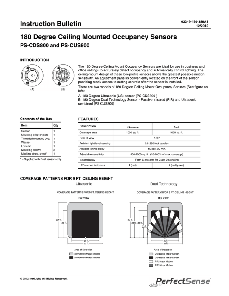
COVERAGE PATTERNS FOR 9 FT. CEILING HEIGHT
© 2012 NexLight. All Rights Reserved.
180°
Ambient light level sensing
Form C contacts for Class 2 signaling
1 (red)
2 (red/green)
180 Degree Ceiling Mounted Occupancy Sensors
Instruction Bulletin
63249-420-386A1
12/2012
STANDARDS AND SPECIFICATIONS
Standards
Ultrasonic
Dual
UL and cUL Listed
FCC Part 15, Home and Office Use (Class B)
California Title 24 Certified
Specifications
Current Consumption @ 24VDC*
Ultrasonic
Dual
Active: 30mA
Active: 33mA
Isolated relay
Contact rating: 1A @24Vdc Resistive
Operating Temperature
32 to 122°F (0 to 50°C)
Humidity
0 to 90% RH non-condensing
*Control power must be provided by the Power Pack or an approved equivalent.
CLASS B FCC STATEMENT
This device complies with Part 15 of the FCC Rules. Operation is subject to the following two conditions: (1) this
device may not cause harmful interference, and (2) this device must accept any interference received, including
interference that may cause undesired operation.
This equipment has been tested and found to comply with the limits for a Class B digital device, pursuant to Part 15
of the FCC Rules. These limits are designed to provide reasonable protection against harmful interference in a
residential installation. This equipment generates, uses, and can radiate radio frequency energy and, if not installed
and used in accordance with the instructions, may cause harmful interference to radio communications. However,
there is no guarantee that interference will not occur in a particular installation. If this equipment does cause
harmful interference to radio or television reception, which can be determined by turning the equipment off and on,
the user is encouraged to try to correct the interference by one or more of the following measures:
Reorient or relocate the receiving antenna.
Increase the separation between the equipment and receiver.
Connect the equipment into an outlet on a circuit different from that to which the receiver is connected.
Consult the dealer or an experienced radio/TV technician for help.
Changes or modifications to this device that are not expressly approved by the manufacturer could void the user's
authority to operate this equipment.
SAFETY PRECAUTIONS
This section contains important safety precautions that must be followed before attempting to install or
maintain electrical equipment. Carefully read and follow the safety precautions below.
HAZARD OF ELECTRIC SHOCK, EXPLOSION, OR ARC FLASH
Apply appropriate personal protective equipment (PPE) and follow safe electrical work practices.
See NFPA 70E.
This equipment must be installed and serviced by qualified electrical personnel.
Turn off all electrical power supplying this equipment before working on or inside the equipment.
Always use a properly rated voltage sensing device to confirm that power is off.
Replace all devices, doors, and covers before turning on power to this equipment.
Failure to follow these instructions will result in death or serious injury.
INSTALLATION
Installation and configuration is simple. The sensor mounts directly to ceilings or ceiling junction
boxes. The sensor can be mounted to a variety of ceiling surfaces, such as acoustical tile,
drywall, plywood, etc. Three possible mounting methods are described in the following
paragraphs.
The sensor has a small directional arrow to indicate the coverage direction.
A. Directional Arrow
2
Determine the direction to mount the sensor and point the arrow in desired coverage direction.
© 2012 NexLight. All Rights Reserved.
63249-420-386A1
12/2012
180 Degree Ceiling Mounted Occupancy Sensors
Instruction Bulletin
Mounting with Supplied Mounting Post
1. Turn off all electrical power supplying this equipment before working on or inside the equipment.
Always use a properly rated voltage sensing device to confirm that power is off.
2. Drill a 7/8-in. dia. hole at the mounting location.
NOTE: For acoustical tile, you can use the threaded mounting post to drill a mounting hole. Press
the cutter end of the mounting post firmly against the tile, and twist the post back and forth.
3. Feed sensor wiring through the mounting post, then twist and lock the mounting post to the back of
the sensor.
4. Insert the mounting post into the hole drilled in step 2. Secure the sensor assembly from the top of
A. Mounting post
the ceiling tile using the supplied washer and lock nut.
B. Lock nut
5. Wire the sensor according to the wiring diagram; follow all applicable national and local electrical
C. Washer
codes.
D. Ceiling tile
Mounting to a Junction Box
1. Turn off all electrical power supplying this equipment before working on or inside the equipment.
Always use a properly rated voltage sensing device to confirm that power is off.
2. Attach the adapter plate to a standard 4-in. ceiling junction box using the two #8 x 32 screws
supplied.
3. Wire the sensor according to the wiring diagram; follow all applicable national and local electrical
codes.
4. Attach the sensor to the adapter plate by inserting the pins on the adapter plate into the keyholes
on the back of the sensor. Rotate the sensor clockwise until it locks in place.
Note: Rotate Clockwise
A. Keyhole pin
B. #8 x 32 screw
C. Junction box
D. Mounting adapter plate
Flush Mounting
Note: Rotate clockwise.
A. Keyhole pin
B. Mounting screw
C. Ceiling
D. Mounting adapter plate
1. Turn off all electrical power supplying this equipment before working on or inside the equipment.
Always use a properly rated voltage sensing device to confirm that power is off.
2. Drill a hole large enough to accommodate wiring at the mounting location.
3. Attach the adapter plate to the ceiling using a secure method, such as with screws and wall
anchors (not provided).
4. Wire the sensor according to the wiring diagram; follow all applicable national and local electrical
codes.
5. Attach the sensor to the adapter plate by inserting the pins on the adapter plate into the
keyholes on the back of the sensor. Rotate the sensor clockwise until it locks in place.
WIRING DIAGRAM
Class 1
Red
Blue
Black
Red
Blue
Black
Red
© 2012 NexLight. All Rights Reserved.
Green (N.C.)
Load
Yellow (Common)
Black
White Power Pack
Red
Orange (N.O.)
Hot
Neutral
Blue
Black
Class 2
Additional
Sensor(s)
(optional)
Contact rating:
1A @ 24 Vdc Resistive
3
180 Degree Ceiling Mounted Occupancy Sensors
Instruction Bulletin
63249-420-386A1
12/2012
OPERATION
1. Restore power to the circuit.
2. Whenever motion is detected the LED(s) on the sensor housing will briefly flash on and the lights
will turn or remain on.
NOTE: When first installed, the sensor may have to warm up for a few minutes before it is fully
operational.
3. Set the Time Delay to the Test setting.
4. Vacate the room until the lights turn off.
5. Re-enter the room. Lights should turn on immediately. If lights do not turn on immediately, verify
correct sensor wiring.
6. Once the sensor is operational, adjust the settings.
SENSOR ADJUSTMENT
Follow the guidelines and refer to the diagrams below to properly adjust the sensor or switches lenses
for proper operation.
NOTE: The sensor employs our patented self adjustment technology which senses occupancy patterns
and continually adjusts the time delay to an optimal setting.
TIME DELAY SETTINGS
DIP Switch Number
1
2
3
4
15 seconds (Test setting)
2 minutes
-
4 minutes
-
6 minutes
-
-
8 minutes
-
10 minutes
-
-
12 minutes
-
-
14 minutes
-
-
-
16 minutes
-
18 minutes (Factory setting)
-
-
20 minutes
-
-
22 minutes
-
-
-
24 minutes
-
-
26 minutes
-
-
-
28 minutes
-
-
-
30 minutes
-
-
-
-
Time Delay:
= On
4
- = Off
© 2012 NexLight. All Rights Reserved.
180 Degree Ceiling Mounted Occupancy Sensors
Instruction Bulletin
Sensor Masking
The sensor comes with a coverage area of 180°. An sheet of masking strips is also provided for
additional masking.
Sensor Masking Example
Sensor with Masking
Field of View from the Top
A. Masking Strip
SUPPORT AND SERVICE
Contact the NexLight Customer Support Center by phone at 218-828-3700.
Contact your local NexLight service representative for repairs or service to your network.
You may also find helpful information on our web site at www.nexlight.com.
NexLight
7878 College Road, Suite 105
PerfectSense is a registered trademark of NexLight Lighting Controls and/or its
affiliates in the United States and/or other countries.
Baxter, MN, 56425
1-218-828-3700
www.nexlight.com
Electrical equipment should be installed, operated, serviced, and maintained only by
qualified personnel. No responsibility is assumed by NexLight and its suppliers for any
consequences arising out of the use of this material.
© 2012 NexLight. All Rights Reserved.
63249-420-386A1
12/2012


