Idaho Generator Interconnection Request Application
advertisement
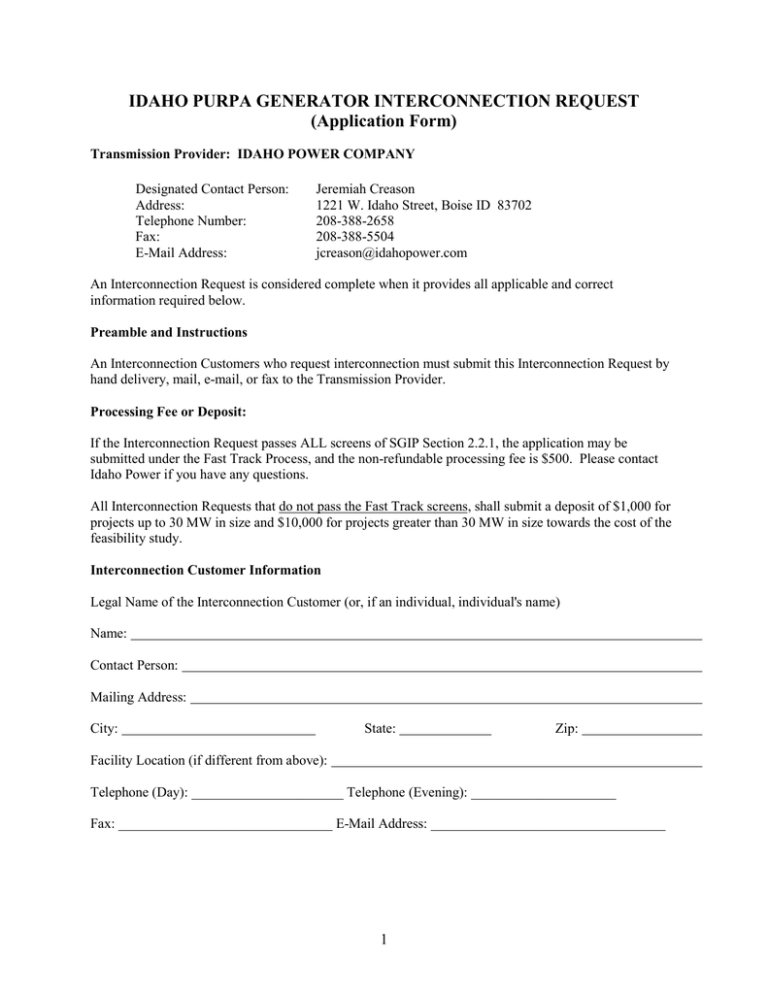
IDAHO PURPA GENERATOR INTERCONNECTION REQUEST (Application Form) Transmission Provider: IDAHO POWER COMPANY Designated Contact Person: Address: Telephone Number: Fax: E-Mail Address: Jeremiah Creason 1221 W. Idaho Street, Boise ID 83702 208-388-2658 208-388-5504 jcreason@idahopower.com An Interconnection Request is considered complete when it provides all applicable and correct information required below. Preamble and Instructions An Interconnection Customers who request interconnection must submit this Interconnection Request by hand delivery, mail, e-mail, or fax to the Transmission Provider. Processing Fee or Deposit: If the Interconnection Request passes ALL screens of SGIP Section 2.2.1, the application may be submitted under the Fast Track Process, and the non-refundable processing fee is $500. Please contact Idaho Power if you have any questions. All Interconnection Requests that do not pass the Fast Track screens, shall submit a deposit of $1,000 for projects up to 30 MW in size and $10,000 for projects greater than 30 MW in size towards the cost of the feasibility study. Interconnection Customer Information Legal Name of the Interconnection Customer (or, if an individual, individual's name) Name: Contact Person: Mailing Address: City: State: Zip: Facility Location (if different from above): Telephone (Day): ______________________ Telephone (Evening): _____________________ Fax: _______________________________ E-Mail Address: __________________________________ 1 Alternative Contact Information (if different from the Interconnection Customer) Contact Name: ___________________________________ Title: ____________________________________________________________________ Address: ______ ___________________________________ ___________________________________ Telephone (Day): ______________________ Telephone (Evening): ______________________ Fax: _____________________________________ E-Mail Address: _________________________ Application is for: ______New Small Generating Facility ______Capacity addition to Existing Small Generating Facility If capacity addition to existing facility, please describe: Will the Small Generating Facility be used for any of the following? To Supply Power to the Interconnection Customer? Yes ___No ___ To Supply Power to Others? Yes ____ No ____ For installations at locations with existing electric service to which the proposed Small Generating Facility will interconnect, provide: (Local Electric Service Provider*) (Existing Account Number*) [*To be provided by the Interconnection Customer if the local electric service provider is different from the Transmission Provider] Requested Point of Interconnection: _____________ Interconnection Customer's Requested In-Service Date: 2 Small Generating Facility Information Data apply only to the Small Generating Facility, not the Interconnection Facilities. Energy Source: ___ Solar ___ Wind ___ Hydro ___ Hydro Type (e.g. Run-of-River):_____________ ___ Diesel ___ Natural Gas ___ Fuel Oil ___ Other (state type) ________________________ Prime Mover: Fuel Cell Recip Engine Microturbine Type of Generator: ____Synchronous ____Induction Gas Turb PV Steam Turb Other ____ Inverter Generator Nameplate Rating: ________kW (Typical) Generator Nameplate kVAR: _______ Interconnection Customer or Customer-Site Load: _________________kW (if none, so state) Typical Reactive Load (if known): _________________ Maximum Physical Export Capability Requested: ______________ kW List components of the Small Generating Facility equipment package that are currently certified: Equipment Type 1. 2. 3. 4. 5. Certifying Entity Is the prime mover compatible with the certified protective relay package? ____Yes ____No Generator (or solar collector) Manufacturer, Model Name & Number: Version Number: Nameplate Output Power Rating in kW: (Summer) _____________ (Winter) ______________ Nameplate Output Power Rating in kVA: (Summer) _____________ (Winter) ______________ Individual Generator Power Factor Rated Power Factor: Leading: _____________Lagging: _______________ Total Number of Generators in wind farm to be interconnected pursuant to this Interconnection Request: __________ Elevation: ______ ___Single phase ___Three phase Inverter Manufacturer, Model Name & Number (if used): _____________________________________ List of adjustable set points for the protective equipment or software: __________________________ Small Generating Facility Characteristic Data (for rotating machines) RPM Frequency: _____________ (*) Neutral Grounding Resistor (If Applicable): ____________ Synchronous Generators: 3 Direct Axis Synchronous Reactance, Xd: _______ P.U. Direct Axis Transient Reactance, X' d: ___________P.U. Direct Axis Subtransient Reactance, X" d: ______________P.U. Negative Sequence Reactance, X2: _________ P.U. Zero Sequence Reactance, X0: ____________ P.U. KVA Base: __________________________ Field Volts: ______________ Field Amperes: ______________ Induction Generators: Motoring Power (kW): ______________ I22t or K (Heating Time Constant): ______________ Rotor Resistance, Rr: ______________ Stator Resistance, Rs: ______________ Stator Reactance, Xs: ______________ Rotor Reactance, Xr: ______________ Magnetizing Reactance, Xm: ______________ Short Circuit Reactance, Xd'': ______________ Exciting Current: ______________ Temperature Rise: ______________ Frame Size: ______________ Design Letter: ______________ Reactive Power Required In Vars (No Load): ______________ Reactive Power Required In Vars (Full Load): ______________ Total Rotating Inertia, H: _____________ Per Unit on kVA Base Note: Please contact the Transmission Provider prior to submitting the Interconnection Request to determine if the specified information above is required. Excitation and Governor System Data for Synchronous Generators Only Provide appropriate IEEE model block diagram of excitation system, governor system and power system stabilizer (PSS) in accordance with the regional reliability council criteria. A PSS may be determined to be required by applicable studies. A copy of the manufacturer's block diagram may not be substituted. Interconnection Facilities Information Will a transformer be used between the generator and the point of common coupling? ___Yes ___No Will the transformer be provided by the Interconnection Customer? ____Yes ____No Transformer Data (If Applicable, for Interconnection Customer-Owned Transformer): Is the transformer: ____single phase _____three phase? Transformer Impedance: _______% on __________kVA Base Size: ___________kVA If Three Phase: Transformer Primary: _____ Volts _____ Delta _____Wye _____ Wye Grounded Transformer Secondary: _____ Volts _____ Delta _____Wye _____ Wye Grounded Transformer Tertiary: _____ Volts _____ Delta _____Wye _____ Wye Grounded Transformer Fuse Data (If Applicable, for Interconnection Customer-Owned Fuse): (Attach copy of fuse manufacturer's Minimum Melt and Total Clearing Time-Current Curves) 4 Manufacturer: __________________ Type: _______________ Size: ________Speed: ______________ Interconnecting Circuit Breaker (if applicable): Manufacturer: ____________________________ Type: __________ Load Rating (Amps): _______ Interrupting Rating (Amps): ________ Trip Speed (Cycles): __________ Interconnection Protective Relays (If Applicable): If Microprocessor-Controlled: List of Functions and Adjustable Setpoints for the protective equipment or software: Setpoint Function Minimum Maximum 1. 2. 3. 4. 5. 6. If Discrete Components: (Enclose Copy of any Proposed Time-Overcurrent Coordination Curves) Manufacturer: Manufacturer: Manufacturer: Manufacturer: Manufacturer: Type: Type: Type: Type: Type: Style/Catalog No.: Style/Catalog No.: Style/Catalog No.: Style/Catalog No.: Style/Catalog No.: Proposed Setting: Proposed Setting: Proposed Setting: Proposed Setting: Proposed Setting: Current Transformer Data (If Applicable): (Enclose Copy of Manufacturer's Excitation and Ratio Correction Curves) Manufacturer: Type: Accuracy Class: Proposed Ratio Connection: ____ Manufacturer: Type: Accuracy Class: Proposed Ratio Connection: ____ Potential Transformer Data (If Applicable): Manufacturer: Type: Accuracy Class: Proposed Ratio Connection: ____ Manufacturer: Type: Accuracy Class: Proposed Ratio Connection: ____ 5 Wind Turbine Generating Facility Required Data 1. Single Machine Equivalent One-Line Diagram Please provide a single machine equivalent one-line diagram similar to figure below: 2. • • • • • • • Interconnection Transmission Line Point of Interconnection (substation or transmission line name): __________________ Line voltage = ______ kV MVA Normal Rating = ______ MVA MVA Emergency Rating = ______ MVA R = ________ ohm or _______ pu on 100 MVA and line kV base (positive sequence) X = ________ ohm or _______ pu on 100 MVA and line kV base (positive sequence) B = ________ μF or _______ pu on 100 MVA and line kV base (positive sequence) 3. Station Transformer (Note: If there are multiple transformers, data for each transformer should be provided) • Nameplate Normal Rating (ONAN/ONAF/ONAF): ______/_____/_____ MVA • Emergency Rating (ONAN/ONAF/ONAF): ______/_____/_____ MVA • Nominal Voltage for each winding (Low /High /Tertiary): _______/_______/_______ kV • Available taps: _____________ (indicate fixed or with LTC), Operating Tap: _______ • Positive sequence ZHL: _____%, ____X/R on transformer self-cooled (ONAN) MVA • Winding connection vector group (delta-wye-gnd, delta-delta, etc.): _________________ 4. • • • • • • • Collector System Equivalent Model Collector system voltage = ________ kV MVA Normal Rating = ______ MVA MVA Emergency Rating = ______ MVA R = _________ ohm or _______ pu on 100 MVA and collector kV base (positive sequence) X = _________ ohm or _______ pu on 100 MVA and collector kV base (positive sequence) B = _________ μF or _______ pu on 100 MVA and collector kV base (positive sequence) Attach a one-line diagram of the collector layout indicating conductor length, type, and size. 5. • • • • • Wind-turbine Generator (WTG) Pad-Mounted Transformer Number of generator step-up transformers: _________________ Individual Nameplate rating: _________________ MVA Individual Emergency rating: _________________ MVA Nominal voltage for each winding (Low /High): _______/_______kV Available taps: __________ (indicate fixed or with LTC), Operating Tap:_______ 6 • • Positive sequence impedance (Z1) _____%, ____X/R on transformer self-cooled MVA Winding connection vector group (delta-wye-gnd, delta-delta, etc.): _________________ 6. Wind-turbine Generator (WTG) Powerflow Data Proposed projects may include one or more WTG Types (See Note 6.1 below). Please provide the following data for each turbine type included in the proposed project: • Number of WTGs: _________________ • Nameplate Rating (each WTG): _________________ MVA • Nameplate Rating (each WTG): _________________ MW • WTG Manufacturer and Model: _________________ • WTG Type (See Note 6.1): _________________ For Type 1 or Type 2 WTGs: • Uncompensated power factor at full load: _______ • Power factor correction capacitors at full load: ______Mvar • Number of shunt stages and size ___________ • Please attach capability curve describing reactive power or power factor range from 0 to full output, including the effect of shunt compensation. For Type 3 and Type 4 WTGs: • Maximum under-excited power factor at full load: _______ • Maximum under-excited power factor at full load: _______ • Control mode: _______________ (voltage control, fixed power factor) (See Note 6.2) • Please attach capability curve describing reactive power or power factor range from 0 to full output. NOTE 6.1 - WTG Type can be one of the following: • Type 1 – Squirrel-cage induction generator • Type 2 – Wound rotor induction machine with variable rotor resistance • Type 3 – Doubly-fed asynchronous generator • Type 4 – Full converter interface NOTE 6.2 - Type 1 and Type 2 WTGs typically operate on fixed power factor mode for a wide range of output level, aided by turbine-side power factor correction capacitors (shunt compensation). With a suitable plant-level controller, Type 3 and Type 4 WTGs may be capable of dynamically varying power factor to contribute to voltage control mode operation, if required by the generator interconnection agreement. Please consult with the WTG manufacturer when in doubt. The interconnection study will determine the voltage control requirements for the project. Plant-level reactive compensation requirements are engineered to meet specific interconnection requirements. WTG reactive capability data described above could significantly impact study results and plant-level reactive compensation requirements. 7. Plant Reactive Power Compensation Provide the following information for plant-level reactive compensation, if applicable: • Individual shunt capacitor and size of each: _____________ MVA 7 • • • • • • • • Dynamic reactive control device, (SVC, STATCOM): ________________________ Control range ___________________________ MVAr (lead and lag) Control mode (e.g., voltage, power factor, reactive power): ____________________ Regulation point or bus _______________________ Description of control strategy Operating characteristic Automatic control model pickup levels and time delay setpoints Indicate if the project includes a plant controller ______________________ 8. Wind-turbine Generator (WTG) Dynamics Data • Provide dynamic models for transient stability analysis in PSLF format using models approved for use by WECC listed in the WECC Approved Dynamic Model Library. • Provide low/high voltage-ride-through dynamic models using an approved PSLF format or the equipment low/high voltage protection settings. • Provide over/under frequency-ride-through dynamic models using an approved PSLF format or the equipment over/under frequency protection settings. Note 8.1 - Please reference the WECC Wind Plant Dynamic Modeling Guidelines for additional information regarding the dynamics modeling needs of Idaho Power and WECC. Photo Voltaic (PV) Generating Facility Required Data 1. Single Machine Equivalent One-Line Diagram Please provide a single machine equivalent one-line diagram similar to figure below: 2. • • • • • Interconnection Transmission Line Point of Interconnection (substation or transmission line name): __________________ Line voltage = ______ kV MVA Normal Rating = ______ MVA MVA Emergency Rating = ______ MVA R = ________ ohm or _______ pu on 100 MVA and line kV base (positive sequence) 8 • • X = ________ ohm or _______ pu on 100 MVA and line kV base (positive sequence) B = ________ μF or _______ pu on 100 MVA and line kV base (positive sequence) 3. Station Transformer (Note: If there are multiple transformers, data for each transformer should be provided) • Nameplate Normal Rating (ONAN/ONAF/ONAF): ______/_____/_____ MVA • Emergency Rating (ONAN/ONAF/ONAF): ______/_____/_____ MVA • Nominal Voltage for each winding (Low /High /Tertiary): _______/_______/_______ kV • Available taps: _____________ (indicate fixed or with LTC), Operating Tap: _______ • Positive sequence ZHL: _____%, ____X/R on transformer self-cooled (ONAN) MVA • Winding connection vector group (delta-wye-gnd, delta-delta, etc.): _________________ 4. • • • • • • • Collector System Equivalent Model Collector system voltage = ________ kV MVA Normal Rating = ______ MVA MVA Emergency Rating = ______ MVA R = _________ ohm or _______ pu on 100 MVA and collector kV base (positive sequence) X = _________ ohm or _______ pu on 100 MVA and collector kV base (positive sequence) B = _________ μF or _______ pu on 100 MVA and collector kV base (positive sequence) Attach a one-line diagram of the collector layout indicating conductor length, type, and size. 5. • Inverter Step-Up Transformer Number of inverter step-up transformers: _________________ • Individual Nameplate rating: _________________ MVA • Individual Emergency rating: _________________ MVA • Nominal voltage for each winding (Low /High): _______/_______kV • Available taps: __________ (indicate fixed or with LTC), Operating Tap:_______ • Positive sequence impedance (Z1) _____%, ____X/R on transformer self-cooled MVA • Winding connection vector group (delta-wye-gnd, delta-delta, etc.): _________________ 6. • • • Inverter and PV Module Data Number of Inverters: _______ Nameplate Rating (each Inverter): ______/______ kW/kVA Describe Inverter reactive capability control mode (i.e. voltage control, power factor, voltage droop control, etc): ____________________________________________________________________ Describe Inverter reactive capability control range maximum and minimum values: ____________________________________________________________________ Provide Reactive Capability Curve (Plot of Reactive Capability vs. Real Power) PV Inverter Short Circuit Current: _______________ Inverter Manufacturer and Model #: _______________ PV Module Manufacturer and Model #: ____________________ • • • • • 7. Plant Reactive Power Compensation Provide the following information for plant-level reactive compensation, if applicable: 9 • • • • • • • • • Individual shunt capacitor and size of each: _____________ MVA Dynamic reactive control device, (SVC, STATCOM): ________________________ Control range ___________________________ MVAr (lead and lag) Control mode (e.g., voltage, power factor, reactive power): ____________________ Regulation point or bus _______________________ Description of control strategy Operating characteristic Automatic control model pickup levels and time delay setpoints Indicate if the project includes a plant controller ______________________ 8. Photo-Voltaic Generator Dynamics Data • Provide dynamic models for transient stability analysis in PSLF format using models approved for use by WECC listed in the “WECC Approved Dynamic Model Library” found at www.wecc.biz. • Provide low/high voltage-ride-thourgh dynamic models using an approved PSLF format or the equipment low/high voltage protection settings. • Provide over/under frequency-ride-thourgh dynamic models using an approved PSLF format or the equipment over/under frequency protection settings. • Please reference the “WECC Solar Plant Dynamic Modeling Guidelines” found at www.wecc.biz for additional information regarding the dynamics modeling needs of Idaho Power and WECC. Small Generating Facility Characteristic Data (for inverter-based machines) Max design fault contribution current: Instantaneous Harmonics Characteristics: Start-up requirements: 10 or RMS? General Information Enclose copy of site electrical one-line diagram showing the configuration of all Small Generating Facility equipment, current and potential circuits, and protection and control schemes. This one-line diagram must be signed and stamped by a licensed Professional Engineer if the Small Generating Facility is larger than 50 kW. Is One-Line Diagram Enclosed? ____Yes ____No Enclose copy of any site documentation that indicates the precise physical location of the proposed Small Generating Facility (e.g., USGS topographic map or other diagram or documentation). Proposed location of protective interface equipment on property (include address if different from the Interconnection Customer's address) ___________________________________________________ Enclose copy of any site documentation that describes and details the operation of the protection and control schemes. Is Available Documentation Enclosed? ___Yes ____No Enclose copies of schematic drawings for all protection and control circuits, relay current circuits, relay potential circuits, and alarm/monitoring circuits (if applicable). Are Schematic Drawings Enclosed? ___Yes ____No Applicant Signature I hereby certify that, to the best of my knowledge, all the information provided in this Interconnection Request is true and correct. For Interconnection Customer: Signed ____________________________________ Date: ____________ Printed ____________________________________ 11
