Φ21 Fall 2006 HW17 Solutions
advertisement

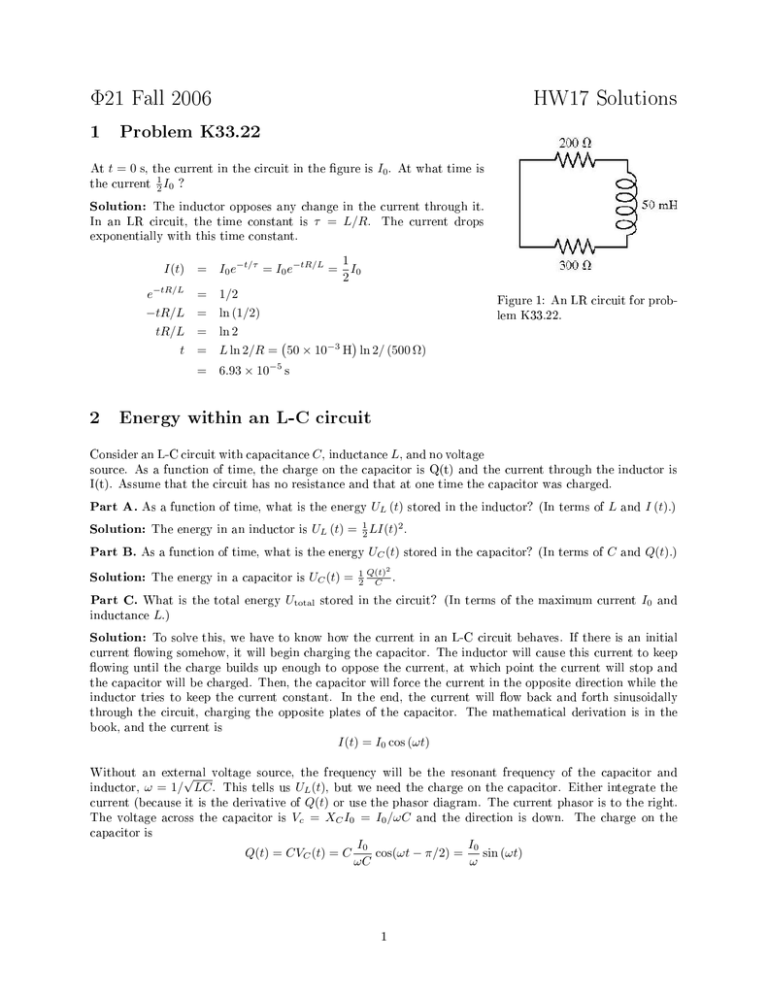
Φ21 Fall 2006 1 At HW17 Solutions Problem K33.22 t = 0 s, the current the current in the circuit in the gure is 1 2 I0 ? I0 . At what time is Solution: The inductor opposes any change in the current through it. τ = L/R. In an LR circuit, the time constant is The current drops exponentially with this time constant. I(t) = e−tR/L −tR/L tR/L t 1 I0 2 = 1/2 = ln (1/2) Figure 1: An LR circuit for problem K33.22. = ln 2 ( ) = L ln 2/R = 50 × 10−3 H ln 2/ (500 Ω) = 2 I0 e−t/τ = I0 e−tR/L = 6.93 × 10⁻⁵ s Energy within an L-C circuit Consider an L-C circuit with capacitance C , inductance L, and no voltage source. As a function of time, the charge on the capacitor is Q(t) and the current through the inductor is I(t). Assume that the circuit has no resistance and that at one time the capacitor was charged. Part A. As a function of time, what is the energy Solution: The energy in an inductor is Part C. What is the total energy inductance stored in the inductor? (In terms of L and I (t).) stored in the capacitor? (In terms of C and Q(t).) UL (t) = 12 LI(t)2 . Part B. As a function of time, what is the energy Solution: The energy in a capacitor is UL (t) UC (t) = Utotal UC (t) 2 1 Q(t) 2 C . stored in the circuit? (In terms of the maximum current I0 and L.) Solution: To solve this, we have to know how the current in an L-C circuit behaves. If there is an initial current owing somehow, it will begin charging the capacitor. The inductor will cause this current to keep owing until the charge builds up enough to oppose the current, at which point the current will stop and the capacitor will be charged. Then, the capacitor will force the current in the opposite direction while the inductor tries to keep the current constant. In the end, the current will ow back and forth sinusoidally through the circuit, charging the opposite plates of the capacitor. The mathematical derivation is in the book, and the current is I(t) = I0 cos (ωt) Without an external voltage source, the frequency will be the resonant frequency of the capacitor and inductor, √ ω = 1/ LC . This tells us UL (t), but we need the charge on the capacitor. Either integrate the Q(t) or use the phasor diagram. The current phasor is to the right. Vc = XC I0 = I0 /ωC and the direction is down. The charge on the current (because it is the derivative of The voltage across the capacitor is capacitor is Q(t) = CVC (t) = C I0 I0 cos(ωt − π/2) = sin (ωt) ωC ω 1 The total energy is then Utotal 1 I02 1 2 LI0 cos2 (ωt) + sin2 (ωt) 2 2C ω 2 1 2 1 LCI02 LI0 cos2 (ωt) + sin2 (ωt) 2 2 C 1 2 LI 2 0 = UL (t) + UC (t) = = = Notice that with no resistance to dissipate the energy, the energy is constant. 3 A Radio Tuning Circuit A radio can be tuned into a particular station frequency by adjusting the capacitance in an L-C circuit. Suppose that the minimum capacitance of a variable capacitor in a radio is 4.11 pF. Part A. What is the inductance L of a coil connected to this capacitor if the oscillation frequency of the L-C circuit is 1.58 MHz, corresponding to one end of the AM radio broadcast band, when the capacitor is set to its minimum capacitance? Solution: The inductance is found from the resonant frequency formula 2 ω 2 = (2πf ) = 1 LC ⇒ L= 1 2 (2πf ) C = 1 2 (2π1.58 × 10⁶ Hz) (4.11 × 10⁻¹² F ) Part B. The frequency at the other end of the broadcast band is 0.533 MHz. capacitance Cmax = 2.47 × 10⁻³ H What is the maximum of the capacitor if the oscillation frequency is adjustable over the range of the broadcast band? Solution: The capacitance is found from the same formula. C= 1 2 (2πf ) L = 1 (2π0.533 × 10⁶ 2 Hz) (2.47 × 10⁻³ H) 2 = 3.61 × 10⁻¹¹ F 4 Problem K35.36 Evaluate VR in the gure at various EMF frequencies. First, let's think about the phasor diagram. Solution: In the series circuit, we know the current is constant, so we draw a current phasor in some direction with length I0 . Then we draw the same direction as the current phasor, with a value of draw the VC phasor at a right angle to VR VR phasor VR = I0 R. in the Then, and in the trailing direction (because voltage lags in a capacitor), which is clockwise from VR . The I length is VC = XC I0 = 0 . Since there is no inductance, we can use the ωC pythagorean theorem to nd the total voltage, which is the vector sum Figure 2: A driven R-C circuit for problem K35.36. of the voltage phasors of the series components. √ √ VR2 Vtotal = Now that we know I0 , we can nd + VC2 = ( 2 (I0 R) + I0 ωC √ )2 = I0 R2 + 1 = E0 ω2 C 2 VR . E0 R VR = I0 R = √ R2 + ω21C 2 Make sure you understand how this formula came about. This is the imprortant part. Now for the numbers. Part A. f = 100 Hz Solution: Part B. = 0.994 V ω = 300 · 2π s−1 and VR = 2.87 V. ω = 1000 · 2π s−1 and VR = 7.07 V. and VR = 9.49 V. f = 3000 Hz Solution: Part E. 1 (200π s−1 )2 (1.59×10⁻⁶ F)2 f = 1000 Hz Solution: Part D. (10 V)(100 Ω) (100 Ω)2 + f = 300 Hz Solution: Part C. ω = 2πf = 200π s−1 and VR = √ ω = 3000 · 2π s−1 f = 10, 000 Hz Solution: ω = 10000 · 2π s−1 and VR = 9.95 V. Notice that the lower frequencies are blocked by the capacitor while the high frequencies get through to the resistor. 3


