Fusing Equipment
Electrical Apparatus
EL Bay-O-Net Current-Limiting Fuse Assembly
240-70
GENERAL
EL Bay-O-Net fuse assembly from
Cooper Power Systems is used to
mount the ELS current-limiting fuse
in fluid-filled distribution apparatus.
The fuse assembly provides the
operating convenience of Cooper
Power Systems versatile Bay-O-Net
expulsion fuse with the energy-limiting
capabilities of the current-limiting
fuses.
The outer housing, inner holder and
handle are made of high strength
thermoplastic for application on
high-voltage systems at elevated
temperatures. An arc follower attached
to the lower end of the fuse aids
loadbreak switching.
installation
No special tools are required. The
outer tube is installed into the
apparatus side wall and gasket sealed.
Refer to Installation and Operating
Instruction Sheet, S240-70-1.
TABLE 1
Electrical Ratings and Characteristics
Description
kV
Voltage Rating
8.3, 15.5, 23.0
ac 60 Hz 1 Minute Withstand
8.3 kV
50
15.5 kV
50
23.0 kV
50
BIL and Full Wave Crest
8.3 kV
150
15.5 kV
150
23.0 kV
150
Minimum Distance from System Ground
8.3 kV
1.1 in. (28 mm)
15.5 kV
1.5 in. (39 mm)
23.0 kV
2.5 in. (64)
Loadbreak Rating
100 A at 80% pf
March 2009 • Supersedes 3/91
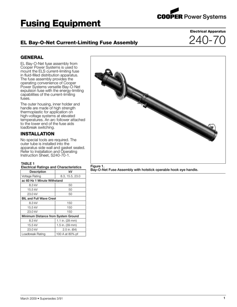
Figure 1.
Bay-O-Net Fuse Assembly with hotstick operable hook eye handle.
1
EL Bay-O-Net Current-Limiting Fuse Assembly
HOOK EYE
Operating Hook Eye
accepts standard hotline
tools for fast, easy fuse
insertion or withdrawal.
HANDLE
Stick-Operable Handle
with cam action seals and
unseals fuse holder assembly and
allows easy removal of fuse.
FUSE HOLDER
Makes fuse a part of bayonet
holder for easy operation.
SEAL COMPRESSION CAM
Releases seal quickly and easily.
BUNA-N SEAL
Provides tight seal that prevents
fluid contamination.
GASKET
Provides tight seal at tank wall.
PRESSURE RELIEF VENT
Equalizes pressure when seal is broken, preventing fluid
expulsion.
FLUID PORT
Allows free flow of fluid inside tube to improve cooling.
LOCKNUT
Allows mounting of assembly on tank wall
at convenient angle for easy insertion and
withdrawal of fuse holder.
COPPER CONTACTS
Spring loaded to ensure positive copperto-copper contact with fuse for cool
connection.
TAPERED FLANGE
7" Tapered Flange retains gasket
seal when compressed during
assembly.
CURRENT-LIMITING FUSE
Oil immersed ELS full-range with
non-gassing technology.
OUTER TUBE
Molded Outer Tube is made of
fiberglass-filled high temperature
thermoplastic molding material.
ARC FOLLOWER
Attached to lower end of fuse
aids in loadbreak switching.
Figure 2.
Cutaway shows feature detail with current-limiting fuse mounted.
2
240-70
5.0"
(127 mm)
FIGURE 3
Line drawing shows application fluid level and dimensional information.
NOTE: Dimensions given are for reference only.
TABLE 2
Dimensional Information in./(mm)
Length
A
B
C
8.3 kV
8.22
(209)
11.31
(287)
11.65
(296)
15.5 and 23.0 kV
16.29
(414)
17.0
(432)
17.25
(438)
ORDERING INFORMATION
To order a Cooper Power Systems'
EL Bay-O-Net fuse assembly, refer to
Tables 3 and 4.
TABLE 3
EL Bay-O-Net Fuse Assemblies
Description
8.3 kV
Assembly with 1/4 inch gasket
Assembly with 3/16 inch gasket
Solid Link Disconnect
15.5 and 23.0 kV
Assembly with 1/4 inch gasket
Assembly with 3/16 inch gasket
Solid Link Disconnect
Catalog Number
4004697B01M
4004697B02M
4025117B51
4004697B03M
4004697B04M
4025117B52
TABLE 4
Replacement Parts
Description
El Bay-O-Net Stabber
(Fuse Holder)
Arc Follower
1/4 inch Gasket
3/16 inch Gasket
Locknut
Catalog Number
4004693B01
4025637A01
0537980C10
0537980C11
4009925A01
3
EL Bay-O-Net Current-Limiting Fuse Assembly
© 2009 Cooper US, Inc. All Rights Reserved.
All Cooper logos, Cooper Power Systems are valuable trademarks of Cooper US, Inc. in the
U.S. and other countries. You are not permitted to use the Cooper Trademarks without the
prior written consent of Cooper US, Inc.
4
2300 Badger Drive
Waukesha, WI 53188 USA
www.cooperpower.com


