Ruckus Wireless AP ZF2942/7942 Quick Setup Guide
advertisement

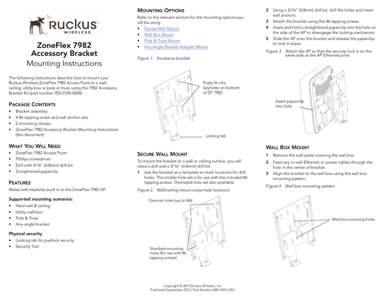
MOUNTING OPTIONS ZoneFlex 7982 Accessory Bracket Mounting Instructions 2 Refer to the relevant section for the mounting options you will be using: • Secure Wall Mount • Wall Box Mount • Pole & Truss Mount • Any-Angle Bracket Adapter Mount 5 Figure 3. Attach the AP so that the security lock is on the same side as the AP Ethernet ports Figure 1. Accessory bracket The following instructions describe how to mount your Ruckus Wireless ZoneFlex 7982 Access Point to a wall, ceiling, utility box or pole or truss using the 7982 Accessory Bracket Kit (part number 902-0100-0000). 3 4 Posts fit into keyholes on bottom of ZF 7982 Insert paperclip into hole PACKAGE CONTENTS • • • • Bracket assembly 4 #6 tapping screw and wall anchor sets 2 mounting clamps ZoneFlex 7982 Accessory Bracket Mounting Instructions (this document) Locking tab WHAT YOU WILL NEED • • • • ZoneFlex 7982 Access Point Phillips screwdriver Drill with 3/16” (4.8mm) drill bit Straightened paperclip Using a 3/16” (4.8mm) drill bit, drill the holes and insert wall anchors. Attach the bracket using the #6 tapping screws. Insert and hold a straightened paperclip into the hole on the side of the AP to disengage the locking mechanism. Slide the AP onto the bracket and release the paperclip to lock in place. WALL BOX MOUNT SECURE WALL MOUNT 1 Remove the wall-plate covering the wall box. 2 FEATURES To mount the bracket to a wall or ceiling surface, you will need a drill and a 3/16” (4.8mm) drill bit. 1 Use the bracket as a template to mark locations for drill holes. The smaller hole set is for use with the included #6 tapping screws. Oversized hole set also available. Feed any in-wall Ethernet or power cables through the hole in the center of bracket. Align the bracket to the wall box using the wall box mounting pattern. Mates with keyholes built in to the ZoneFlex 7982 AP. Figure 2. Wall/ceiling mount screw hole locations Supported mounting scenarios: • • • • Locking tab for padlock security Security Torx Figure 4. Wall box mounting pattern Oversize holes (up to M6) Hard wall & ceiling Utility wall box Pole & Truss Any-angle bracket Wall box mounting holes Physical security • • 3 Standard mounting holes (for use with #6 tapping screws) Copyright © 2012 Ruckus Wireless, Inc. Published September 2012, Part Number 800-70412-001 4 5 6 Mount the bracket to the wall box using the original wallplate screws. Insert and hold a straightened paperclip into the hole on the side of the AP to disengage the locking mechanism. Slide the AP onto the bracket and release the paperclip to lock in place. POLE & TRUSS MOUNT 1 Wrap mounting clamps around the pole or truss and insert ends into bracket. The holes used for pole and truss clamps are shown in Figure 5. Figure 5. Mounting strap holes for pole and truss mount ANY-ANGLE BRACKET ADAPTER MOUNT PHYSICAL SECURITY 1 The locking tab is provided for physical security. During AP mounting/un-mounting, the locking tab must be in the unlocked position. 2 3 4 5 6 Mount the any-angle bracket adapter to the mounting surface (wall or pole). • Any-angle bracket adapter part #901-0182-0003. Mount the accessory bracket to the any-angle bracket adapter using the four M4 machine screws. Mount the AP to the accessory bracket. Tighten clamp screws. Insert and hold a straightened paperclip into the hole on the side of the AP to disengage the locking mechanism. Slide the AP onto the bracket and release the paperclip to lock in place. Figure 7. Any-angle bracket adapter mounting Holes for pole mounting straps Note the following options and requirements: • • • If physical security is not required, the locking tab can be left in the unlocked position and secured with the Torx screw provided. Once mounted to the bracket, the AP can be physically secured by rotating the locking tab toward the AP, into the locked position as shown in Figure 8. A Torx screw or padlock can be used to secure the locking tab in the locked position. When un-mounting AP, make sure the locking tab is rotated away from the AP. Figure 8. Locking tab in locked position Holes for truss mounting straps Hole for security Torx screw 2 3 4 Tighten the clamp screws to secure the bracket to the pole or truss. Insert and hold a straightened paperclip into the hole on the side of the AP to disengage the locking mechanism. Slide the AP onto the bracket and release the paperclip to lock in place. Padlock eye Figure 9. Locking tab in locked position with padlock Figure 6. Pole mounting Copyright © 2012 Ruckus Wireless, Inc. Published September 2012, Part Number 800-70412-001


