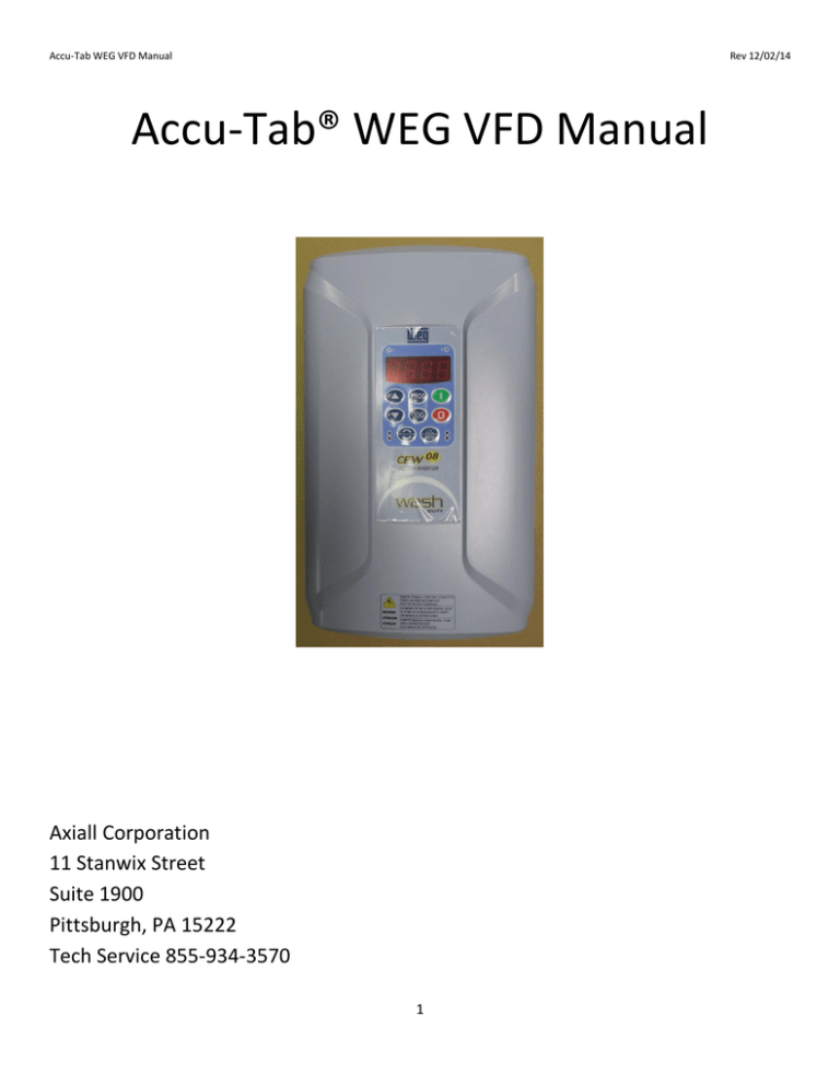
Accu-Tab® WEG VFD Manual
advertisement

Accu-Tab WEG VFD Manual Rev 12/02/14 Accu-Tab® WEG VFD Manual Axiall Corporation 11 Stanwix Street Suite 1900 Pittsburgh, PA 15222 Tech Service 855-934-3570 1 Accu-Tab WEG VFD Manual Rev 12/02/14 Electrical Connections 1. Open front cover. 2. Follow diagram below for the proper electrical connections. 3. Replace front cover. + Jumper for ENABLE Terminals #1 to #5 4-20 mA from Controller Dry Contact Start From PowerPro Board - K1 & K1 2000 P Board - #7 & #8 Supply Power 1 ph #L1, L2 3 ph #L1, L2 & L3 Power out to Pump Wiring Connections Power input 3 – phase 1 – phase Terminals L1 Terminals L1 L2 L2 Power out to pump Always 3-phase output Terminals U V Control wiring Dry Contact Start 4-20 mA Input Jumper Terminals Terminals Terminal “minus” “plus” L3 W # 1 and #5 #4 and #5 #5 #6 2 Accu-Tab WEG VFD Manual Rev 12/02/14 System Boot-Up Red Light on means Remote Green Light on means Local LOC REM Local – set hz. with Pump Rotation Green light – Shows forward DO NOT CHANGE!! Password to make changes 1. 2. 3. 4. 5. Arrow Up to P000 to enter Password for adjustments. Press Program PROG . A “0” will appear, meaning the key pad is locked. Arrow Up to change to “5” to unlock the key pad. Press Program PROG to save. P0000 will show again. Press ???? to lock key pad???? PROG Set minimum and maximum Output (Hz) 1. Arrow Up to P133 to set the minimum output. PROG 2. Press Program to display minimum Hz value. 3. Arrow Up/Down to set the minimum output in Hz. This value MUST be above xx Hz. to prevent over-heating of the motor. It also MUST be above the pump stall flow speed (deadhead). This must be determined experimentally. 4. Press Program PROG to save. 5. Arrow Up to P134 to set the maximum output. 3 Accu-Tab WEG VFD Manual Rev 12/02/14 6. Press Program PROG to display maximum Hz value. 7. Arrow Up/Down to set the maximum output in Hz. Set to 61 Hz. 8. Press Program PROG to save. Example of Hz display. To display actual Hz for operation 1. Arrow Down to P002 to display actual Hz output, then Program Will be zero when no 4-20 mA input or system not operating. PROG to display. To set the VFD to span the 4-20 input between the Min and Max Hz 1. 2. 3. 4. Arrow Up/Down to P233. Press Program PROG to display value. Factory default is “1”. Arrow Down to change to “0”. Press Program PROG to save. 4 Accu-Tab WEG VFD Manual Rev 12/02/14 Initial Set-Up – Completed at factory when mounted on a system A new VFD will need to have this completed before operation, and/or if a new pump is installed. 1. Parameter P220 – set value to “1 for always remote. 2. Parameter P222 – set value to “1” for Frequency location reference. 3. Parameter P235 – set value to “1” for 4-20 mA input. 4. 5. 6. 7. 8. 9. Obtain the following information from the pump motor data plate and input the value. Parameter P399 – Rated Motor Efficiency Parameter P400 – Rated Motor Voltage Parameter P401 – Rated Motor FLA Parameter P402 – Rated Motor Speed Parameter P403 – Rated Motor Frequency Parameter P404 – Rated Motor Hp 10. Parameter P407 – Rated Motor Power Factor 5


