Motor Circuit Protectors
Motor Protection Selection Tables
Class 601
www.schneider-electric.us
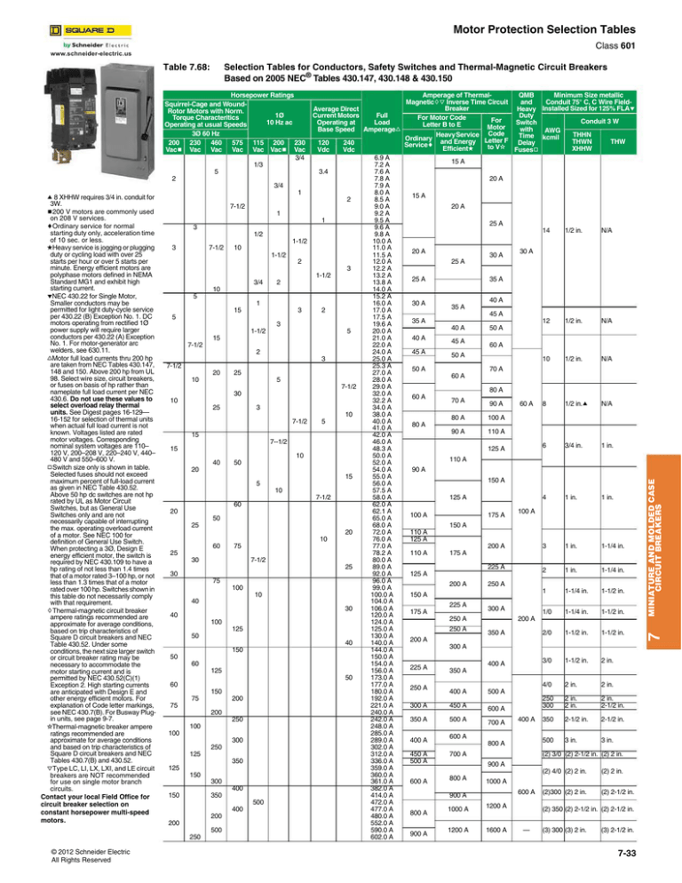
Selection Tables for Conductors, Safety Switches and Thermal-Magnetic Circuit Breakers
Based on 2005 NEC® Tables 430.147, 430.148 & 430.150
200
Vacb
3Ø 60 Hz
230
460
Vac Vac
575
Vac
115 200
Vac Vacb
Average Direct
Current Motors
Full
Operating at
Load
Base Speed Amperagef
230
Vac
3/4
120
Vdc
240
Vdc
1/3
5
3.4
2
3/4
a 8 XHHW requires 3/4 in. conduit for
3W.
b200 V motors are commonly used
on 208 V services.
cOrdinary service for normal
starting duty only, acceleration time
of 10 sec. or less.
dHeavy service is jogging or plugging
duty or cycling load with over 25
starts per hour or over 5 starts per
minute. Energy efficient motors are
polyphase motors defined in NEMA
Standard MG1 and exhibit high
starting current.
eNEC 430.22 for Single Motor,
Smaller conductors may be
permitted for light duty-cycle service
per 430.22 (B) Exception No. 1. DC
motors operating from rectified 1Ø
power supply will require larger
conductors per 430.22 (A) Exception
No. 1. For motor-generator arc
welders, see 630.11.
fMotor full load currents thru 200 hp
are taken from NEC Tables 430.147,
148 and 150. Above 200 hp from UL
98. Select wire size, circuit breakers,
or fuses on basis of hp rather than
nameplate full load current per NEC
430.6. Do not use these values to
select overload relay thermal
units. See Digest pages 16-129—
16-152 for selection of thermal units
when actual full load current is not
known. Voltages listed are rated
motor voltages. Corresponding
nominal system voltages are 110–
120 V, 200–208 V, 220–240 V, 440–
480 V and 550–600 V.
gSwitch size only is shown in table.
Selected fuses should not exceed
maximum percent of full-load current
as given in NEC Table 430.52.
Above 50 hp dc switches are not hp
rated by UL as Motor Circuit
Switches, but as General Use
Switches only and are not
necessarily capable of interrupting
the max. operating overload current
of a motor. See NEC 100 for
definition of General Use Switch.
When protecting a 3Ø, Design E
energy efficient motor, the switch is
required by NEC 430.109 to have a
hp rating of not less than 1.4 times
that of a motor rated 3–100 hp, or not
less than 1.3 times that of a motor
rated over 100 hp. Switches shown in
this table do not necessarily comply
with that requirement.
hThermal-magnetic circuit breaker
ampere ratings recommended are
approximate for average conditions,
based on trip characteristics of
Square D circuit breakers and NEC
Table 430.52. Under some
conditions, the next size larger switch
or circuit breaker rating may be
necessary to accommodate the
motor starting current and is
permitted by NEC 430.52(C)(1)
Exception 2. High starting currents
are anticipated with Design E and
other energy efficient motors. For
explanation of Code letter markings,
see NEC 430.7(B). For Busway Plugin units, see page 9-7.
iThermal-magnetic breaker ampere
ratings recommended are
approximate for average conditions
and based on trip characteristics of
Square D circuit breakers and NEC
Tables 430.7(B) and 430.52.
jType LC, LI, LX, LXI, and LE circuit
breakers are NOT recommended
for use on single motor branch
circuits.
Contact your local Field Office for
circuit breaker selection on
constant horsepower multi-speed
motors.
1
2
7-1/2
1
1
3
1/2
1-1/2
3
7-1/2
1-1/2
2
3
1-1/2
3/4
2
10
5
1
15
3
2
5
3
1-1/2
5
15
7-1/2
2
3
7-1/2
20
25
10
5
7-1/2
30
10
25
3
10
7-1/2
5
15
7--1/2
15
10
40
50
20
15
5
10
7-1/2
60
20
50
25
20
10
60
75
25
30
7-1/2
25
30
75
100
10
40
30
40
100
125
50
40
150
50
60
125
50
60
150
75
200
75
200
250
100
100
300
250
125
350
125
150
300
400
150
350
500
400
200
200
500
250
© 2012 Schneider Electric
All Rights Reserved
10
6.9 A
7.2 A
7.6 A
7.8 A
7.9 A
8.0 A
8.5 A
9.0 A
9.2 A
9.5 A
9.6 A
9.8 A
10.0 A
11.0 A
11.5 A
12.0 A
12.2 A
13.2 A
13.8 A
14.0 A
15.2 A
16.0 A
17.0 A
17.5 A
19.6 A
20.0 A
21.0 A
22.0 A
24.0 A
25.0 A
25.3 A
27.0 A
28.0 A
29.0 A
32.0 A
32.2 A
34.0 A
38.0 A
40.0 A
41.0 A
42.0 A
46.0 A
48.3 A
50.0 A
52.0 A
54.0 A
55.0 A
56.0 A
57.5 A
58.0 A
62.0 A
62.1 A
65.0 A
68.0 A
72.0 A
76.0 A
77.0 A
78.2 A
80.0 A
89.0 A
92.0 A
96.0 A
99.0 A
100.0 A
104.0 A
106.0 A
120.0 A
124.0 A
125.0 A
130.0 A
140.0 A
144.0 A
150.0 A
154.0 A
156.0 A
173.0 A
177.0 A
180.0 A
192.0 A
221.0 A
240.0 A
242.0 A
248.0 A
285.0 A
289.0 A
302.0 A
312.0 A
336.0 A
359.0 A
360.0 A
361.0 A
382.0 A
414.0 A
472.0 A
477.0 A
480.0 A
552.0 A
590.0 A
602.0 A
Amperage of ThermalMinimum Size metallic
QMB
Magnetichj Inverse Time Circuit
Conduit 75° C, C Wire Fieldand
Breaker
Heavy Installed Sized for 125% FLAe
Duty
For Motor Code
For
Conduit 3 W
Switch
Letter B to E
Motor
with
AWG
Code
Heavy
Service
THHN
Time
Ordinary
Letter F Delay kcmil
THWN
THW
Servicec and Energy
to Vi Fusesg
Efficientd
XHHW
15 A
20 A
15 A
20 A
25 A
20 A
30 A
14
1/2 in.
N/A
12
1/2 in.
N/A
10
1/2 in.
N/A
8
1/2 in.a
N/A
6
3/4 in.
1 in.
4
1 in.
1 in.
3
1 in.
1-1/4 in.
2
1 in.
1-1/4 in.
1
1-1/4 in.
1-1/2 in.
1/0
1-1/4 in.
1-1/2 in.
2/0
1-1/2 in.
1-1/2 in.
3/0
1-1/2 in.
2 in.
4/0
2 in.
2 in.
250
300
2 in.
2 in.
2 in.
2-1/2 in.
350
2-1/2 in.
2-1/2 in.
500
3 in.
3 in.
30 A
25 A
25 A
30 A
35 A
40 A
35 A
45 A
35 A
40 A
40 A
45 A
45 A
50 A
60 A
50 A
50 A
70 A
60 A
80 A
60 A
70 A
90 A
80 A
100 A
90 A
110 A
60 A
80 A
125 A
110 A
90 A
150 A
125 A
100 A
175 A
100 A
150 A
110 A
125 A
200 A
110 A
175 A
225 A
125 A
200 A
250 A
150 A
225 A
175 A
300 A
250 A
250 A
200 A
350 A
200 A
300 A
225 A
250 A
400 A
350 A
400 A
300 A
450 A
350 A
500 A
400 A
450 A
500 A
600 A
500 A
600 A
700 A
600 A
800 A
700 A
(2) 3/0 (2) 2-1/2 in. (2) 2 in.
900 A
800 A
900 A
1000 A
1200 A
(2) 4/0 (2) 2 in.
(2) 2 in.
(2)300 (2) 2 in.
(2) 2-1/2 in.
1000 A
600 A
900 A
800 A
400 A
1200 A
1600 A
(2) 350 (2) 2-1/2 in. (2) 2-1/2 in.
—
(3) 300 (3) 2 in.
(3) 2-1/2 in.
7-33
MINIATURE AND MOLDED CASE
CIRCUIT BREAKERS
Horsepower Ratings
Squirrel-Cage and WoundRotor Motors with Norm.
1Ø
Torque Characteritics
10 Hz ac
Operating at usual Speeds
7
Table 7.68:


