115 VAC - 3.3 AMP HEATER AND FAN ASSEMBLY KIT
DoorKing Part Number
1601-154
This kit is designed for all 6050, 6100, 6300, 9050, 9100, 9150, 9310 models and model 9000 -115 VAC ONLY gate operators. For
cold weather climates where temperatures routinely drop below 40°F (4°C). A built-in thermostat will automatically control the
temperature inside operator housing.
High Voltage AC Input Power for a Gate Operator with a Heater
DO NOT use the “high voltage wire size and distance requirements” table in the Installation/Owner’s manuals to determine the high
voltage AC input power wire size and distance requirements for the gate operator because of a much greater current draw when
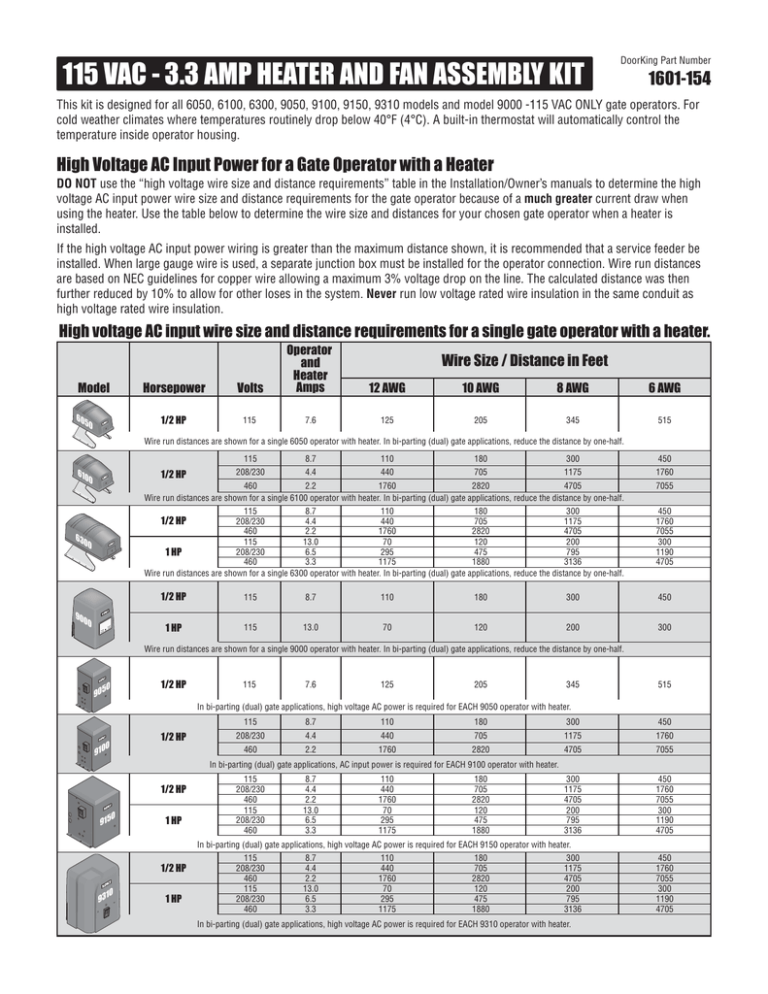
using the heater. Use the table below to determine the wire size and distances for your chosen gate operator when a heater is
installed.
If the high voltage AC input power wiring is greater than the maximum distance shown, it is recommended that a service feeder be
installed. When large gauge wire is used, a separate junction box must be installed for the operator connection. Wire run distances
are based on NEC guidelines for copper wire allowing a maximum 3% voltage drop on the line. The calculated distance was then
further reduced by 10% to allow for other loses in the system. Never run low voltage rated wire insulation in the same conduit as
high voltage rated wire insulation.
High voltage AC input wire size and distance requirements for a single gate operator with a heater.
Model
60
50
Horsepower
Volts
Operator
and
Heater
Amps
1/2 HP
115
7.6
Wire Size / Distance in Feet
12 AWG
10 AWG
8 AWG
6 AWG
125
205
345
515
Wire run distances are shown for a single 6050 operator with heater. In bi-parting (dual) gate applications, reduce the distance by one-half.
610
0
1/2 HP
115
8.7
110
180
300
450
208/230
4.4
440
705
1175
1760
1760
4705
460
2820
2.2
Wire run distances are shown for a single 6100 operator with heater. In bi-parting (dual) gate applications, reduce the distance by one-half.
7055
180
300
8.7
110
115
705
1175
4.4
440
208/230
2820
4705
2.2
1760
460
70
13.0
120
200
115
295
6.5
475
795
208/230
1 HP
3.3
1175
1880
3136
460
Wire run distances are shown for a single 6300 operator with heater. In bi-parting (dual) gate applications, reduce the distance by one-half.
450
1760
7055
300
1190
4705
1/2 HP
63
00
90
00
1/2 HP
115
8.7
110
180
300
450
1 HP
115
13.0
70
120
200
300
Wire run distances are shown for a single 9000 operator with heater. In bi-parting (dual) gate applications, reduce the distance by one-half.
50
90
1/2 HP
115
7.6
125
205
345
515
In bi-parting (dual) gate applications, high voltage AC power is required for EACH 9050 operator with heater.
1/2 HP
0
910
115
8.7
110
180
300
450
208/230
4.4
440
705
1175
1760
460
2.2
1760
2820
4705
7055
300
1175
4705
200
795
3136
450
1760
7055
300
1190
4705
In bi-parting (dual) gate applications, AC input power is required for EACH 9100 operator with heater.
1/2 HP
0
915
1 HP
115
208/230
460
115
208/230
460
8.7
4.4
2.2
13.0
6.5
3.3
110
440
1760
70
295
1175
180
705
2820
120
475
1880
In bi-parting (dual) gate applications, high voltage AC power is required for EACH 9150 operator with heater.
1/2 HP
10
93
1 HP
115
208/230
460
115
208/230
460
8.7
4.4
2.2
13.0
6.5
3.3
110
440
1760
70
295
1175
180
705
2820
120
475
1880
300
1175
4705
200
795
3136
In bi-parting (dual) gate applications, high voltage AC power is required for EACH 9310 operator with heater.
450
1760
7055
300
1190
4705
Installation of Heater
Kit Includes: Heater / mounting plate and 2 locknuts.
DoorKing Part Number
1601-154
3 Mounting Heater
Locate existing threaded studs in operator.
Heater MUST be on mounted on mounting
plate with 2 supplied locknuts.
Existing
Operator
Threaded
Stud
Locknut
(Supplied)
1 Shut off ALL power to operator
Thermostat Sensor
Mo
un
Pla ting
te
O
N
O
FF
Turn off the DC convenience open power switch
on certain operator models first then shut off the
AC input power to the operator from the circuit
breaker.
5
4
Power Wires
DA
NG
HO
T!
2 Heater Location
Determine heater’s mounting location.
ER
Note: Keep wires away
from the heater vent.
Existing
Operator
Threaded
Stud
Locknut
(Supplied)
9150
9050, 9100
4 Operator Power Terminal Connection
Connect the heater power wires according to operator AC power type.
DANGER
Hot
Neutral
HIGH VOLTAGE!
1
9310
2
1
2
3
115
VAC
Hot
6300
Note for 6050/6100/6300/9000 Bi-Parting Dual Gates:
Run two (AWG 16-600 volt insulation) power wires
from the primary operator power terminal through the
interconnection cable conduit to power the secondary
operator’s heater. DO NOT wire secondary heater
directly to the secondary operator’s terminal or
damage will occur.
Neutral
9000 115 VAC ONLY
4
5
6050, 6100
115 VAC Models
208/230/460 VAC Models
5 Heater Switch
ON - Normal setting. Automatically turns the heater and fan ON when
ON
the temperature drops below 40°F (4°C) inside the operator, and turns
the heater and fan OFF when the temperature rises above 55°F (13°C)
inside the operator.
OFF
9210-165-F-5-11
OFF - Turns the heater/fan off.
Copyright 2011 DoorKing, Inc. All rights reserved.
120 Glasgow Avenue
Inglewood, California 90301 U.S.A.

