Experiment 5: Mesh Current Analysis
advertisement

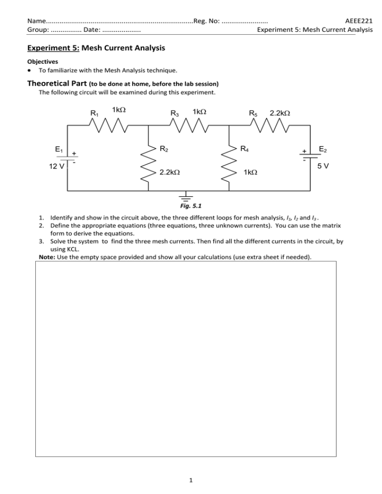
Name............................................................................Reg. No: ........................ AEEE221 Group: ................ Date: .................... Experiment 5: Mesh Current Analysis Experiment 5: Mesh Current Analysis Objectives To familiarize with the Mesh Analysis technique. Theoretical Part (to be done at home, before the lab session) The following circuit will be examined during this experiment. R1 E1 12 V + - 1k R3 1k R2 R5 R4 2.2k 1k 2.2k + - E2 5V Fig. 5.1 1. Identify and show in the circuit above, the three different loops for mesh analysis, I1, I2 and I3 . 2. Define the appropriate equations (three equations, three unknown currents). You can use the matrix form to derive the equations. 3. Solve the system to find the three mesh currents. Then find all the different currents in the circuit, by using KCL. Note: Use the empty space provided and show all your calculations (use extra sheet if needed). 1 AEEE221 Experiment 5: Mesh Current Analysis 4. Now proceed with simple analysis techniques to calculate the remaining parameters in the circuit and complete the Table 5.1 E1=12v E2=5v PE1= PE2= PR3= VR1= VR2= VR3= VR4= VR5= IR1=I1= IR2= IR3=I2= IR4= IR5=I3= Table 5.1 5. Discuss the use of Mesh current and Node Voltage Methods in Circuit Analysis. 2 AEEE221 Experiment 5: Mesh Current Analysis Practical Part Note: the symbol (`) is used to distinguish the experimental values from the calculated. Your instructor will provide you with all the components needed to construct the circuit shown in Figure 5.1. 1. Complete the following table according to the measured values of the components you are going to use for the circuit in Figure 5.1. E`1= E`2= R`1= R`3= R`4= R`5= R`2= Table 5.2 2. Construct the circuit shown in Figure 5.1. 3. Measure all the voltage drops in the circuit and record the values in Table 5.3. 4. Then, use the measured values of resistors and voltage drops, to calculate the corresponding currents. Use the space provided in Table 5.3. 5. Also calculate the power delivered by the sources and the power dissipated by R3, in order to complete the practical part. E`1= E`2= P`E1= P`E2= P`R3= V`R1= V`R2= V`R3= V`R4= V`R5= I`R1= I`R2= I`R3= I`R4= I`R5= Table 5.3 6. Compare your results by calculating the %Difference between calculated and experimental values (Table 5.4). Comment on your results. %Difference IR1 IR3 IR5 Comments: 3

