A Division of MagiQ Technologies Inc.
Product specification
4000 Series PXIe CW Synthesizers
Features
•
•
•
•
•
•
•
Three versions: 4061, 4062 and 4122
Frequencies up to 12 GHz
Calibrated level range: -10 dBm to +10 dBm
Max available power > +15 dbm (typ)
Single slot 3U PXIe module
Low harmonics and spurious signals
Excellent phase noise
Applications
•
•
•
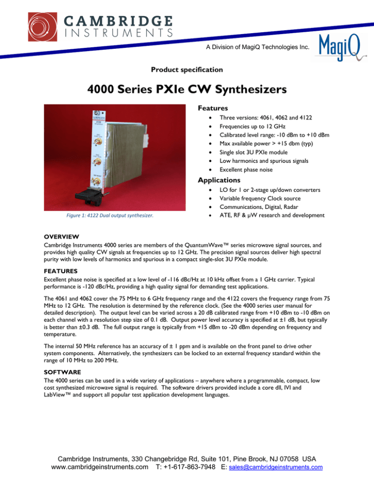
Figure 1: 4122 Dual output synthesizer.
•
LO for 1 or 2-stage up/down converters
Variable frequency Clock source
Communications, Digital, Radar
ATE, RF & µW research and development
OVERVIEW
Cambridge Instruments 4000 series are members of the QuantumWave™ series microwave signal sources, and
provides high quality CW signals at frequencies up to 12 GHz. The precision signal sources deliver high spectral
purity with low levels of harmonics and spurious in a compact single-slot 3U PXIe module.
FEATURES
Excellent phase noise is specified at a low level of -116 dBc/Hz at 10 kHz offset from a 1 GHz carrier. Typical
performance is -120 dBc/Hz, providing a high quality signal for demanding test applications.
The 4061 and 4062 cover the 75 MHz to 6 GHz frequency range and the 4122 covers the frequency range from 75
MHz to 12 GHz. The resolution is determined by the reference clock. (See the 4000 series user manual for
detailed description). The output level can be varied across a 20 dB calibrated range from +10 dBm to -10 dBm on
each channel with a resolution step size of 0.1 dB. Output power level accuracy is specified at ±1 dB, but typically
is better than ±0.3 dB. The full output range is typically from +15 dBm to -20 dBm depending on frequency and
temperature.
The internal 50 MHz reference has an accuracy of ± 1 ppm and is available on the front panel to drive other
system components. Alternatively, the synthesizers can be locked to an external frequency standard within the
range of 10 MHz to 200 MHz.
SOFTWARE
The 4000 series can be used in a wide variety of applications – anywhere where a programmable, compact, low
cost synthesized microwave signal is required. The software drivers provided include a core dll, IVI and
LabView™ and support all popular test application development languages.
Cambridge Instruments, 330 Changebridge Rd, Suite 101, Pine Brook, NJ 07058 USA
www.cambridgeinstruments.com T: +1-617-863-7948 E: sales@cambridgeinstruments.com
To facilitate manual operation for experimentation or
application development, an intuitive graphical user
interface, GUI, is provided.
By selecting the
corresponding slot number, multiple 4000 series
synthesizers can be viewed and controlled from a
single GUI.
To simplify manual test scenarios, independent
up/down steps can be entered through the GUI on
each channel for both frequency and level parameters.
The step sizes can be of any value within the resolution
of the instrument.
Figure 2: 4122 Graphical User Interface showing module in Slot 2
4000 SERIES
Products in the 4000 series range of microwave PXIe synthesizers include:
•
4061: 6 GHz PXIe Single Channel Synthesizer. Provides a 75 MHz to 6 GHz synthesizer in a single PXIe slot.
•
4062: 6 GHz PXIe Dual Channel Synthesizer. Provides two fully independent 75 MHz to 6 GHz synthesizers
in a single PXIe slot.
•
4122: 12 GHZ PXIe Dual Channel Synthesizer. Provides independent 75 MHz to 6GHz and 6 to 12GHz
synthesizers.
BLOCK DIAGRAM
Filter
X2
9.0 < Fout < 12.0 GHz
6.0 GHz to 12.0 GHz
Synthesizer
Switch
Switch
Atten
Filter
6.0 < Fout < 9.0 GHz
Filter
Synthesizer
Switch
X2
Filter
Bank
Switch
Atten
Filter
0.075 GHz to 6.0 GHz
EXT REF CLK
Switch
INT
50MHz
FPGA
PXI 10MHz
PXIE BACKPLANE
Figure 3: 4122 Simplified Block Diagram
Copyright© MagiQ Technologies Inc. All rights reserved. Specifications are subject to change. Rev-A 09/14
Page 2
SPECIFCATIONS
Frequency
4061: Single Channel:
4062: Two Channels:
4122: Two Channels:
75 MHz to 6 GHz
Channel 1: 75 MHz to 6 GHz
Channel 1: 75 MHz to 6 GHz,
Resolution:
Dependent on Reference Frequency, fref/2
Channel 2: 75 MHz to 6 GHz
Channel 2: 6 GHz to 12 GHz
22+N
(Where N = 0 for 6–12 GHz and increases by 1 each octave below 6 GHz. See examples below)
Ref Frequency:
Range: 375 MHz – 750 MHz, N = 4
Range: 0.75 GHz – 1.5 GHz, N=3
Range: 1.5 GHz – 3 GHz, N=2
Range: 3 GHz – 6 GHz, N=1
Range: 6 GHz – 12 GHz. N=0
Accuracy:
Switching Speed:
50 MHz
10 MHz
(External)
(Internal/External)
.015 Hz
0.75 Hz
.03 Hz
1.49 Hz
0.6 Hz
2.98 Hz
1.19 Hz
5.96 Hz
2.38 Hz
11.92 Hz
Same as Reference Frequency
80 MHz
(External)
1.19 Hz
2.38 Hz
4.77 Hz
9.54 Hz
19.07 Hz
250 µs (from receipt of instruction, settled to within 0.1% of final frequency)
Amplitude
Calibrated Range:
Accuracy:
+10 dBm to -10 dBm
±1 dBm across full temp range 0˚C to 55˚C (< 0.3 dBm typical)
Uncalibrated O/P Range:
+15 dBm to -20 dBm (typical, frequency and temperature dependent)
Maximum Available Power
(Typical)
Resolution:
Level Switching Time:
VSWR:
0.1 dB
50 µs (to ±0.5 db, typical)
< 1.5:1 (nominal)
Spectral Purity:
Broadband Noise Floor:
75 MHz to 6 GHz:
6 GHz to 12 GHz:
< 150 dBc/Hz
< 140 dBc/Hz
Harmonically related spurs:
75 MHz to 6 GHz:
6 GHz to 12 GHz:
Non Harmonic spurs:
< -20 dBc, (typ < -30 dBc @ +10 dBm & < -40 dBc @ 0 dBm)
< -20 dbc, (typ < -30 dBc @ +10 dBm & < -35 dBc @ 0 dBm)
< -50 dBc, (typ < -65 dBc)
Phase noise:
1GHz @ 10 kHz offset:
9 GHz @ 10 kHz offset:
-116 dBc/Hz (Internal Reference)
-96 dBc/Hz (Internal Reference)
Copyright© MagiQ Technologies Inc. All rights reserved. Specifications are subject to change. Rev-A 09/14
Page 3
Typical SSB Phase noise
@10 kHz offset:
(Internal Reference)
1 GHz
3 GHz
6 GHz
Channel 1
-120 dBc/Hz
-112 dBc/Hz
-102 dBc/Hz
6 GHz
9 GHz
12 GHz
Channel 2
-104 dBc/Hz
-100 dBc/Hz
-97 dBc/Hz
Typical Average Phase
Noise
(Phase Noise Data
Courtesy NoiseXT)
Ch1 to Ch2 Isolation:
Card to card Isolation
>70 db @ >1 MHz separation (typical, 4062 and 4122 only )
>90 db
Frequency Reference:
Internal:
Frequency:
Accuracy:
Long-term stability:
Output Power:
Connector:
SSB Phase Noise:
PXI Backplane:
External Ref In:
Frequency Range:
Input Power Range:
Connector:
50 MHz
±1x10⁻⁶, (0 to 50˚C after 30 mins warm-up time)
±3x10⁻⁶, over 10 years
0 dBm nominal into 50 Ω
SMA female (Internal Ref Out or External Ref In)
-145 dBc/Hz @ 10 kHz offset
Can be locked to PXI 10 MHz clock (Caution: May degrade accuracy and
phase noise).
10 MHz to 200 MHz (See User Guide for Inputs above 80 MHz)
-3 dBm min to +10 dBm max
SMA female (Internal Ref Out or External Ref In)
Physical and Environmental:
Temperature:
Operating:
Storage:
Warm-up time:
Control Interface:
EMC:
Safety:
Size:
Weight:
Power:
0 to 55˚C (Chassis fan operating)
-20 to 85˚C
30 minutes
PXI Express
FCC Class A, EMC Directive 2004/108/EC, Canadian ICES-001, AS/NZS
CISPR 11
IEC 61010
3U PXIe single-slot (210 mm x 22 mm x 130 mm)
< 1 lb, (< 0,45 kg)
< 18 W
System Requirements:
Operating System:
Software:
32 or 64 bit Windows 7, 8, 8.1
Microsoft .NET Framework 4.0, NI-VISA 5.4
Copyright© MagiQ Technologies Inc. All rights reserved. Specifications are subject to change. Rev-A 09/14
Page 4


