Multimeter Tutorial: Measuring Voltage, Resistance, and Testing Components
advertisement
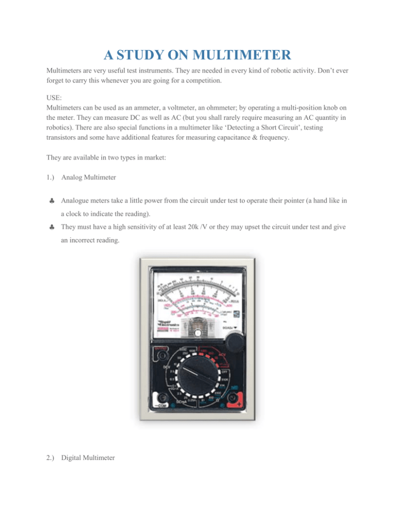
A STUDY ON MULTIMETER Multimeters are very useful test instruments. They are needed in every kind of robotic activity. Don’t ever forget to carry this whenever you are going for a competition. USE: Multimeters can be used as an ammeter, a voltmeter, an ohmmeter; by operating a multi-position knob on the meter. They can measure DC as well as AC (but you shall rarely require measuring an AC quantity in robotics). There are also special functions in a multimeter like ‘Detecting a Short Circuit’, testing transistors and some have additional features for measuring capacitance & frequency. They are available in two types in market: 1.) § Analog Multimeter Analogue meters take a little power from the circuit under test to operate their pointer (a hand like in a clock to indicate the reading). § They must have a high sensitivity of at least 20k /V or they may upset the circuit under test and give an incorrect reading. 2.) Digital Multimeter § All digital meters contain a battery to power the display so they use virtually no power from the circuit under test. § They have a digital display as shown. There DC voltage ranges have a very high resistance (usually called input impedance) of 1M or more, usually 10 M , and they are very unlikely to affect the circuit under test. Here we will have discussion on digital multimeter (as they are commonly used). There are three sockets of wire, the black lead is always connected into the socket marked COM, short form for COMMON. The red lead is connected into the socket labeled V mA. The 10A socket is very rarely used. Measuring resistance with a multimeter To measure the resistance of a component it must not be connected in a circuit. If you try to measure resistance of components in a circuit you will obtain false readings (even if the supply is disconnected) and you may damage the multimeter. The techniques used for each type of meter are very different so they are treated separately: Measuring resistance with a DIGITAL multimeter 1. Set the meter to a resistance range greater than you expect the resistance to be. Notice that the meter display shows "off the scale" (usually blank except for a 1 on the left). Don't worry, this is not a fault, it is correct - the resistance of air is very high! 2. Touch the meter probes together and check that the meter reads zero. If it doesn't read zero, turn the switch to 'Set Zero' if your meter has this and try again. 3. Put the probes across the component. Avoid touching more than one contact at a time or your resistance will upset the reading! If the meter reads 1, this means that the resistance is more than the maximum which can be measured on this range and you may need to switch to a new position, 2000 k or so, to take a reading. Note: It is recommended purchasing a multimeter with a 'continuity' feature built in. This mode allows us to 'tone' out circuits. In this mode, if you touch the two probes together (or there is a short circuit), you should hear a tone indicating that there is a direct connection between one probe and the other (obviously - you have them touching!). This feature is used countless times during trouble shooting. Measuring Voltage with Voltmeter 1. Select a voltage range with a maximum greater than you expect the reading to be. If the reading goes off the scale immediately disconnect and select a higher range. 2. Connect the red (positive +) lead to the point you where you need to measure the voltage 3. The black lead can be left permanently connected to 0V while you use the red lead as a probe to measure voltages at various points. (The black lead can be fitted by using a crocodile clip.) Similarly you can measure the current by choosing a suitable range. If it displays a ‘1’ at left, choose a higher current range. Testing a diode with a DIGITAL multimeter § Digital multimeters have a special setting for testing a diode, usually labeled with the diode symbol. § Connect the red (+) lead to the anode and the black (-) to the cathode. The diode should conduct and the meter will display a value (usually the voltage across the diode in mV, 1000mV = 1V). § Reverse the connections. The diode should NOT conduct this way so the meter will display "off the scale" (usually blank except for a 1 on the left). Testing a transistor with a multimeter Set a digital multimeter to diode test and an analogue multimeter to a low resistance range such as × 10 ohm as described above for testing a diode. Test each pair of leads both ways (six tests in total): § The base-emitter (BE) junction should behave like a diode and conduct one way only. § The base-collector (BC) junction should behave like a diode and conduct one way only. § The collector-emitter (CE) should not conduct either way. NOTE: Conducting in one way simply means it will behave as a short circuit and The diagram shows how the junctions behave in an NPN transistor. The diodes are reversed in a PNP transistor but the same test procedure can be used. Some multimeters have a 'transistor test' function; please refer to the instructions supplied with the meter for details. Source : http://www.botskool.com/tutorials/electronics/general-electronics/ multimeter
