Moving Charge and Faraday`s Law
advertisement

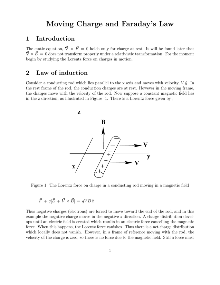
Moving Charge and Faraday’s Law 1 Introduction ~ × E ~ = 0 holds only for charge at rest. It will be found later that The static equation, ∇ ~ ~ ∇ × E = 0 does not transform properly under a relativistic transformation. For the moment begin by studying the Lorentz force on charges in motion. 2 Law of induction Consider a conducting rod which lies parallel to the x axis and moves with velocity, V ŷ. In the rest frame of the rod, the conduction charges are at rest. However in the moving frame, the charges move with the velocity of the rod. Now suppose a constant magnetic field lies in the z direction, as illustrated in Figure 1. There is a Lorentz force given by ; z B V + + x + + y V Figure 1: The Lorentz force on charge in a conducting rod moving in a magnetic field ~ + V~ × B] ~ = qV B x̂ F~ + q[E Thus negative charges (electrons) are forced to move toward the end of the rod, and in this example the negative charge moves in the negative x direction. A charge distribution develops until an electric field is created which results in an electric force cancelling the magnetic force. When this happens, the Lorentz force vanishes. Thus there is a net charge distribution which locally does not vanish. However, in a frame of reference moving with the rod, the velocity of the charge is zero, so there is no force due to the magnetic field. Still a force must 1 z B1 B2 V y x 1 2 V Figure 2: Forces generated on a current loop moving in a magnetic field still exist in this frame because a charge distribution develops along the rod. Since a force due to the magnetic field requires a charge velocity, the force must come from an electric field. However, there is no electric field in the frame moving with the rod. Therefore, the field transformation between the rest and moving frames of reference generates an electric field which has the value obtained from the Lorentz force equation. ~ ′ = −V ~′×B ~′ E In the prime frame the velocity of the rod is zero, but there is an E field which moves positive ~ ′ = −V ~ . Therefore the electric and magnetic fields charge in the x̂ direction. In this frame V are connected by transformations between moving coordinate frames Now suppose the conducting rod is bent into a current loop. This is illustrated in Figure 2. The force on different elements of the loop can then be determined. Given the geometry, the only forces which which matter come from elements 1 and 2, as shown in the figure. The work done in moving the charge around the loop is found to be; H F~ · d~s = qV [B1 − B2 ]L The integral around the loop is taken by the right hand rule. The length of the elements 1 and 2 is L. Now divide by the charge, q. H ~ · d~s = V [B1 − B2 ]L E Obviously if [B1 − B2 ] = 0 no work is done and no charge moves. However, the right hand side is identified as the electromotive force around the loop, EMF . This is the energy per 2 z B1 B2 2 V y x V 1 Figure 3: The change of flux for a moving loop through a variable magnetic field unit charge which flows in the circuit. Since energy is put into the circuit, it must come from the kinetic energy of motion of the loop. There is a current flow around the loop which ~ . Along side 1 for example, there is a force in the -ŷ direction we assume has velocity, V ~ ~ given by V × B. This force then acts as a resistance to the initial motion of the loop. For example, if a force drives the loop at constant velocity, this resistive force due to the current flow balances the driving force. The magnetic flux through the loop in figure 3 is; φ = R ~ · d~σ = B R dx dy B(x, y) Differentiate this flux by time, and look at figure 3. The loop area does not change, but it moves so that the lighter hatched area is replaced by the darker one. Thus the change in flux is; ∆φ = B2 L dy − B1 Ldy = −[B1 − B2 ]Ldy Then use dy = V; dt dφ = −LV [B1 − B2 ] dt Comparing this equation to the equation for the EMF above, one finds that; H ~ · d~s = − d E dt R ~ · d~σ B Then use stokes theorem to convert the integral on the left hand side to an intergral over the enclosed area. Since this area is arbitrary, the integrands are equal. ~ ~ ×E ~ = − ∂B ∇ ∂t 3 B A θ ω Figure 4: The EMF generated by a rotating conducting loop. This geometry is used to ~ produce an alternating current. The area vector of the loop is A. The use of the partial derivative here may not be so clear, and will be addressed later. The above equation is Faraday’s Law, which can also be written as; EMF = − 3 3.1 ∂φ ∂t Examples Rotating loop in a static magnetic field Suppose we consider a loop rotating in a static magnetic field as illustrated in Figure 4. The flux through the loop is; φ = R ~ · d~σ = B cos(θ) B R dσ = B(W L) cos(θ) By Faraday’s Law; EMF = − dφ = B(W L)ω sin(θ) dt Here ω = dθ . The EMF and thus the current, has a harmonic form as expected (ie an dt alternating current is produced). 3.2 Homopolar Generator On the other hand, a homopolar generator generates a direct current. A type of homopolar generator was devised by Faraday (Faraday Disk) and is shown in Figure 5. A conducting disk is rotated between the poles of a magnetic field, and an EMF is generated between the 4 Eddy Current B EMF ω Figure 5: The geometry of the Faraday Disk which generates a direct current radial edge of the disk and its axis. A constant rotational speed generates a constant EMF. This is most easily seen by using the Lorentz force acting on the rotating charges in the disk. r̂ θ̂ ẑ ~ = V ~ ×B ~ = 0 rω 0 E 0 0 B ~ = rωBr̂ E The EMF generated between the axis and the rim of the disk is; EMF = Ra dr rωB = ωBa2 /2 0 This assumes that the field is constant over the entire disk. The potential difference is low but the current flow can be large. However, the efficiency of the Faraday Disk is low as the current is not completely radial due to eddy currents as shown in Figure 5. A more efficient homopolar generator uses a uniform, static magnetic field through the entire disk surface. Modern designs can create DC currents up to mega-amps. 5 Pos. Charge Collected Gas at High Plasma Temp. ++ +++++ + + + + + + + Magnetic Field +++++++ + + + + + + + Into Page +++++ ++ Neg. Charge Collected Figure 6: The geometry of an MHD Generator 4 MHD Generator A magnetodynamic (MHD) generator has no moving, mechanical components. Gas at high temperature strips into ions and electrons, and this plasma is then allowed to expand at high velocity through a magnetic field which separates the ions and electrons, creating an EMF between the conducting plates. These generators are highly efficient. However, they produce direct currents and have other practical problems, Figure 6. 5 Energy Conservation As discussed previously, the current induced by Faraday’s Law in a moving rod, Figure 7, interacts with the magentic field causing a force which acts as a resistance to the motion of the rod. The EMF due to the motion is; EMF = − d dt R ~ · d~σ = BLV. B The current which flows in the circuit expends power in the resistor equal to I (EMF ) = IBLV . The current flowing in the circuit is I = (EMF )/R from which the force F on the wire due to the current flow is; F = ILB The power input required to keep the velocity constant (or decelerate the rod) is; P = F V = ILBV This shows conservation of energy. 6 B F B V R V F Figure 7: Energy conservation in a system with a moving conducting rod in a constant magnetic field 6 Lenz’s law The total system energy is conserved if we take into account the energy loss by dissipation. To conserve energy when an EMF is created, a current flow is induced which tends to keep the flux through a current loop constant. This induced current creates a force which resists the motion of the loop (if the loop moves), and a magnetic field opposite to the field which initially produced the flux. This essentially removes energy from the mechanical motion and reduces the energy in the field. This energy goes into the movement of charge (EMF ) in the loop. 7 Conductivity As voltage is increased between conductors embedded in a medium, the flow of charge between the conductors increases in linear proportion to the voltage. This is Ohm’s law, which is usually expressed as; ~ J~ = σ E ~ is the electric field in the medium, and In the above equation, J~ is the current density, E σ is the conductivity of the medium. The resistivity of the medium is the inverse of the conductivity, ρ = 1/σ. Conductivity is measured in Siemens (one siemen equals one ampere produced by a potential difference of one volt). The Ohm is the unit of resistance. Table 1 gives some resistivities and indicates the sensitivity of the resistivity to temperature, α where σT σT ′ = . Generally as the temperature decreases the resistivity also decreases. 1 + α(T − T ′ ) Although, with the exception of superconductors, resistance remains non-zero even at 0◦ K. Superconductors in addition to having zero resistance at some finite temperature also expell magnetic fields from the interior of the superconductor, the Meisner effect. 7 Table 1: Resistivities and temperature coefficients for some metals Metal Resistivity Temperarture ◦ Ω-m 20 C Coefficient K−1 Silver 1.59 × 10⁻⁸ 0.0038 Copper 1.72 × 10⁻⁸ 0.0039 −8 Gold 2.44 × 10 0.0034 Aluminum 2.82 × 10⁻⁸ 0.0039 −8 Tungsten 5.60 × 10 0.0045 −8 Zinc 5.90 × 10 0.0037 Nickel 6.99 × 10⁻⁸ 0.0059 A I I L Figure 8: The connection between resistance and resistivity The resistance of a filament along an electric field line is illustrated in Figure 8. The cross sectional area of the filament is A, and its length is L. This is shown in the figure. The differential resistance in terms of the resistivity is then; dR = ρ dL A All metals are resonably good conductors because electrons in the outer atomic shells are losely bound and can easily travel in the potential wells of a metalic crystal. This is illustrated in Figure 9. The temperature dependence of the resistivity is given by the Bloch-Grüneisen equation. ρ(T ) = ρ(0) + A( ΘT )n R ΘR R /T 0 dx xn (e − 1)(1 − e−x ) x In the above, ΘR is the Debye temperature and n is an integer which depends on the electron interactions in the material (ie electron scattering by phonons, electron scattering from atomic electrons, or the electron-electron Coulomb interaction). In a conductor, the resistivity can be described as a complex number for an alternating current, the real component due to a Ohmic resistance and the imaginary component due to reactance (energy placed in temporary storage in the electric and magnetic fields). 8 Conduction Band Potential Surface Atomic Lattice Figure 9: A schematic showing a crystal lattice and an electron conduction band The current flows along the field lines. Therefore in a 3-dimensional object we must find the field and equipotential lines in order to obtain the resistance. As previously, this requires the solution of Laplace’s equation, ∇2 V = 0, subject to boundary conditions in order to obtain the potential function, V. In the electrostatic case the value of the potential, Vs , or its normal derivative on the conducting surfaces is required. The derivative normal to the surface gives the charge on the surface of a conductor. To obtain the resistance, consider the current flow. Specification of a constant potential in a conductor, and specification of the current is equivalent to specification of the charge. This is because the value of E at a conducting surface is equal to the normal derivative of the potential. In electrostatics; Q = ǫ R da ∂V ∂n In the case of currents, use the conductivity σ = J/E, where J is the current density and E is the electric field. I = R da (σ ∂V ) ∂n Thus there is a connection between the capacitance of a set of conductors and the resistance between them. Recall that the capacitance is C = Q/V . If the capacitance is known and σ is constant, the resistance is obtained by multiplying the inverse of the capacitance by σ/ǫ = 1/ρǫ. Thus; R = V /I = Q/IC = ρǫ/C = ρǫV /Q 8 Example of a resistance between concentric spheres A resistive medium fills the space between 2 concentric spheres as illustrated in Figure 10. The potential between the spheres is obtained in spherical coordinates; Q V = κr 9 ρ ε a b Figure 10: The geometry to find the resistance between 2 conducting spheres ~ = κ Q2 r̂ E r The potential difference is then; Va − Vb = κQ [1/ra − 1/rb ] The capacitance is; a rb C = Q/V = 4πǫr ra − rb The resistance between the spheres is; ρ R = ρǫ/C = 4π [1/ra − 1/rb ] This could have been obtained from the resistivity using the equation for the resistance of an filament as in the above section, dR = ρ dL/A. ~ at the surface. where A is the surface area of the conductor perpendicular to E dR = ρdr 4πr 2 Integration over r between a and b gives the result obtained above. 10


