JJMIE
Volume 3, Number 2, June. 2009
ISSN 1995-6665
Pages 151 -156
Jordan Journal of Mechanical and Industrial Engineering
Mathematical Model of Inductive Effect on the Multi-motors
Synchronization Systems
Ali Akayleh *, Samarai Ahmed, Al-Soud Mohammed
Department of Electrical Engineering, Tafila Technical University, Tafila - Jordan.
Abstract
Systems of synchronous rotation with AC machines depend on the equality of speed of two or more induction motors
(mechanical or non mechanical-shaft connected) with the existence of load differences allocated on these shafts. The most
popular ones among non-mechanical-shaft synchronization systems are the synchronization systems with auxiliary machines,
electrical shaft systems, and the electromagnetic working shaft systems. In this work, using MATLAB – SIMULINK
program, we suggest a mathematical model which represents a synchronous drive with electromagnetic working shaft system.
The model will be tested with two similar induction motors 5hp, 50 Hz, 380 line voltage. Principle of operation and
advantages related to the synchronous capability and recovery time for the electromagnetic working shaft system in deferent
operational stats were also studied.
© 2009 Jordan Journal of Mechanical and Industrial Engineering. All rights reserved
Keywords: Mathematical Model; Synchronous Capability; Induction Motors; Electromagnetic Shaft
1. Introduction
*
Systems of synchronous rotation are most used in
cranes, cutting tool machines, and lifting machines [1].
The main performance of synchronization systems is very
much related to the synchronous capability (speed
synchronization, with maximum different loads on the
motors shafts), and the required synchronization process
time (recovery time).
When difference in load distribution is high, the system
requires more synchronous capability. Therefore, the
synchronous capability should be determined for any
change in rated load, variation in load distribution, and
rated power parameters. Accordingly, synchronous
capability differs according to the connection, which links
up the motors in the system. If the connection is direct
mechanical one, then synchronous capability is unlimited.
If the connection is non-mechanical, then synchronous
capability will depend on the load distribution and the type
of the control element connected between the main motors.
Electromagnetic working shaft system is recently the
most applicable system compared to other synchronization
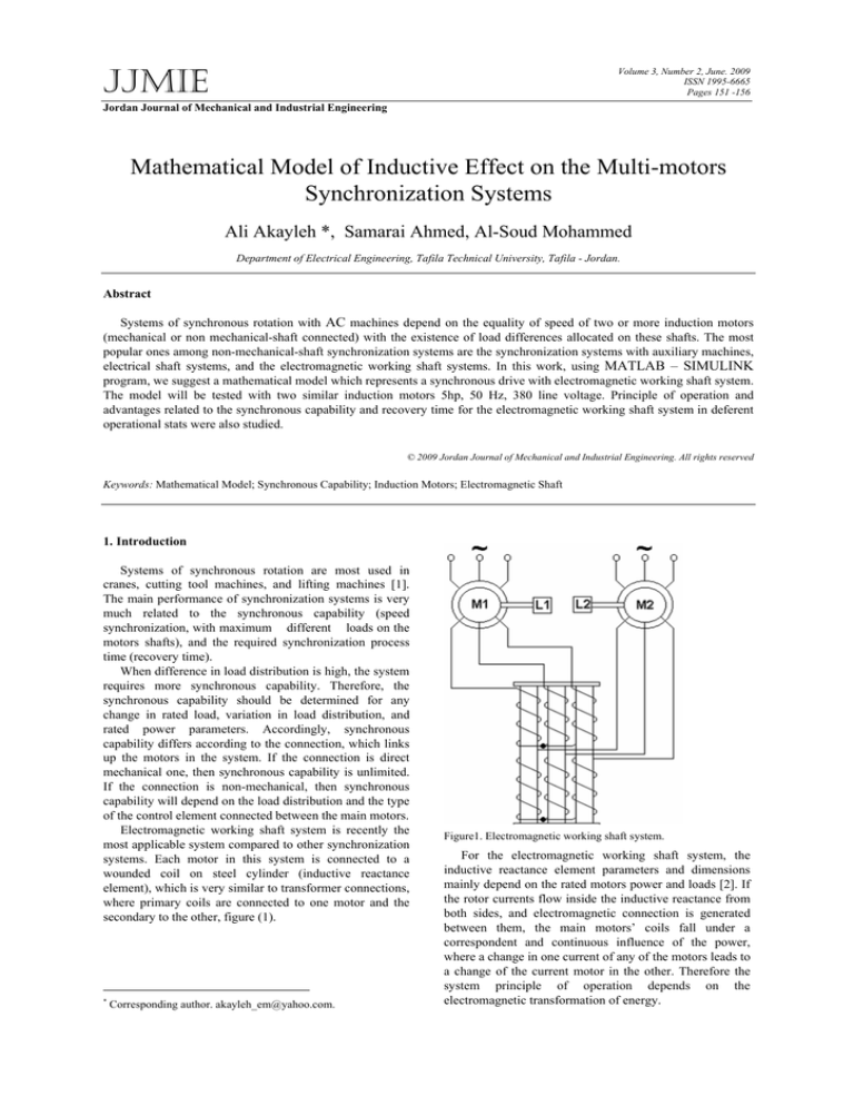
systems. Each motor in this system is connected to a
wounded coil on steel cylinder (inductive reactance
element), which is very similar to transformer connections,
where primary coils are connected to one motor and the
secondary to the other, figure (1).
*
Corresponding author. akayleh_em@yahoo.com.
Figure1. Electromagnetic working shaft system.
For the electromagnetic working shaft system, the
inductive reactance element parameters and dimensions
mainly depend on the rated motors power and loads [2]. If
the rotor currents flow inside the inductive reactance from
both sides, and electromagnetic connection is generated
between them, the main motors’ coils fall under a
correspondent and continuous influence of the power,
where a change in one current of any of the motors leads to
a change of the current motor in the other. Therefore the
system principle of operation depends on the
electromagnetic transformation of energy.
152
© 2009 Jordan Journal of Mechanical and Industrial Engineering. All rights reserved - Volume 3, Number 2 (ISSN 1995-6665)
If the loads on motors shafts are equal, ( L1 = L2 ) ,
the rotor currents moving inside the inductive reactance
are also equal, and the electromagnetic fields generated in
those rotors are equal in quantity and are opposite in
direction, so there will be no connection between the
rotors, and the motors are operating as individual induction
motors.
If the loads and the motors shafts are not
equal ( L 1 ≠ L 2 ) , then the rotor currents and the
electromagnetic fields will also change. This will lead to
an electromagnetic connection amongst the inductive
element of the rotor’s coils that will be used to
synchronization of the motors speed.
When the system is started with any load difference,
there will be a great difference in the starting currents on
the inductive reactance terminals, this difference will cause
the smallest loaded motor to operate as a generator causing
a decrease in the electromotive force value, and therefore
the motor speed will decrease rapidly. Therefore the
current will increase. The increased current will reverse the
previous operation.
This variation will cause a system vibration. And to
overcome this effect, the system should start when the
loads are equal.
2. System Equivalent Circuit
To derive the control equations for the system, it is
possible to use the simplified equivalent circuit given in
Figure (2) [3].
When the loads become equal, the rotors and stators phase
shift will be equal too ( α 1 = α 2 ) and
( Δ α = 0 ).
Where:
T A (1 ) =
R o′ + R 2′
2 R M′
+
S
S
R1 +
2
2 R M′
R o′ + R 2′
+
S
S
R1 +
. 1 + c o sΔ α
2
+ X
k
+ X o′ +
2
2 X M′
S
α 1 ,α 2 .
Phase angles between the stator and rotor
windings of main motors.
From the equivalent circuit Figure (2), the balance
equations for the phase rotor voltage can be calculated as
follows:
(1)
E′ = I ′ Z + Z + I ′ Z
[ d M ] 2( 2) M
E 2′ ( 2) = I 2′ ( 2 ) [Z d + Z M ] + I 2′ (1) Z M
2 (1)
2 (1)
Where:
Z d = ( R1 +
RM
ZM =
S
(2)
R′
R 2′
+ o ) + J ( X k + X o′ )
S
S
XM
, X k = ( X1 + X 2′ )
+ j
S
From (1 and 2) the rotor current for the first motor can be
calculated as:
I'2(1) =
1 ⎡ E′2(1) + E′2(2) E′2(1) − E′2(2) ⎤
+
⎥
2 ⎢⎣ Z d + 2Z M
Zd
⎦⎥
(3)
Based on [4 and 5], if the first motor is determined as a
reference
motor
of
the
system,
so;
( E 2′ (1)
= E 2′ , E 2′ ( 2 ) = E 2′ e j Δ α
),
and
the
torque of the first motor can be calculated as:
Figure 2. System equivalent circuit.
Where:
R1, X 1 :
Stator resistance and inductive reactance of
first and second motors.
R 2′ , X 2′
: Rotor Resistance and inductive reactance of
first and second motors.
R o′ , X o′
: Resistance and inductive reactance of
inductive element.
R M′ , X M′
: Resistance and inductive reactance of
magnetizing circuit of inductive element.
Rc, X c
: Resistance and inductive reactance of
magnetizing circuit of induction motor.
E 2′ ( 1 ) , E 2′ ( 2 ) : Rotor phase voltage in the first and the
second motors.
I 2′ ( 1 ) , I 2′ ( 2 )
motors.
S: Slip.
: Rotor current of the first and the second
T1 =
m E 2′
2ω o
2
[I& ′
+ I 2′ ( 2 )
2 (1 )
]
(4)
Where:
m: number of phase, I&2′ (1) . Conjugate value of the first
rotor current.
If we add the value of rotor current ( I 2′ (1) ) and its
conjugate ( I&2′ (1) ), and after some transformations the
torque (equation 4) will be:
T1 =
m E 2′
2ω o
2
[T A
+ T S . Sin Δ α
]
(5)
Where:
T A = T A (1 ) + T A ( 2 ) -
Asynchronous part of the
torque.
T S = T S (1 ) + T S ( 2 )
torque.
- Synchronous part of the
© 2009 Jordan Journal of Mechanical and Industrial Engineering. All rights reserved - Volume 3, Number 2 (ISSN 1995-6665)
Xk + Xo′ +
TS(1) =
R′ + R′ 2R′
R1 + o 2 + M
S
S
R1 +
T A( 2) =
TS (2) =
Hz,
2
2XM′
X1=
S
2
+ Xk + Xo′ +
X k + X o′
R ′ + R 2′
R1 + o
S
2.252 Ω,
Xc
Ω,
R 2′
=1.083
= 76.8 Ω., J=0.02 kg.m²),
R o′ , X o′ , X M′ ),
R M′ , L1, L2), feedback ( Δ s . Δ α , S1,
element
parameters (
The main input of this block is the output data signal of
general data block. Using this data, the torque equations,
(5 and 6) were built Figure (4).
2
2
2
+ X k + X o′
2
If the second motor is determine as a reference
( E 2′ ( 2 )
= E 2′
and E 2′ (1)
= E 2′ e jΔα
),
then
the
motor torque can be determined similar to the first motor
but with negative part of synchronous torque [5].
mE2′
T2 =
[TA − TS .SinΔα ]
2ωo
Ω,
3.2. Block 2 (System Main Equations Block)
2
+ X k + X o′
R1=1.115
inputs (
S2) , and parameters.
Where:
L1. Load torque of first motor. L2. Load torque of second
motor.
S
R o′ + R 2′
. 1 − cos Δ α
S
R ′ + R 2′
R1 + o
S
X 2′ =
inductive
2
2XM′
VL=380V,
153
2
(6)
3. System Block Diagrams
Using the main equivalent circuit equations, rotational
dynamic torque equations, angular speed, and angular
positions equations, the mathematical model of the
electromagnetic working shaft system has been built [6].
This model (see figure 3) consists of three blocks each of
them has a specific functions.
Figure 4. System main equations block
3.3. Block 3 (Error Calculation Block)
The error calculation block input consists of torque
equations (T1, T2), load torque value (L1, L2), and
general data signal incoming from the first block
Usingjdynamicjtorquejequation:
( T in − T L = J
Figure 3. System block diagram.
3.1. Block 1 (General Data Block)
This block was built using difference basic data such as
the similar induction motors parameters, (5hp, 4 pole 50
dω
dt
) and relationships between
angular speed, difference between windings phase
shift and slip ( ω 1 , ω 2 , Δ α , S 1 , S 2 ), the
synchronous process, synchronous capability and
recovery time of the system are calculated.
154
© 2009 Jordan Journal of Mechanical and Industrial Engineering. All rights reserved - Volume 3, Number 2 (ISSN 1995-6665)
The above mentioned output values of this block
diagram are presented as the main system response and as
the feedback values, which goes back to first block.
inductive reactance coils will be equal in quantity and will
be opposite in direction. Therefore, the motors will also
operate as individual motors with equal speeds,
(ω 1 = ω 2 ) ,Figure (7).
Figure 7. Speed response when equal loads.
If the magnetizing resistance is not equal to zero
(
Figure 5. Error calculation block.
R M′
≠ 0), and the loads on the shafts are not
equal, ( L 1 ≠ L 2 ) , and then the electromotive forces
generated in inductive reactance coils will be not equal.
This will produce energy difference in the common rotor
4. System Operation and Test
According to [6], and based on practical applications of
electromagnetic working shaft systems, the inductive
reactance element power factor (COS α ) ranges between
0.7 and 0.85 , and relationships inductive reactance
parameters with resistance R’M are joined .
X M′ = tan α .RM′
X o′ = R o′ = ( 0 . 1 − 0 . 2 ) R M′
circuit,
( Δ E = E 2′ ( 2 ) − E 2′ ( 1 ) )
.
This energy will decrease the speed of the motor with
the lowest effect until it leads to equality of speeds in both
motors. In this case, the system will be tested with three
′ (Rated) , Figure (8).
values (0.5, 1.0, 1.5) RM
For our system model, using specific method [6], the
model will be tested with the below inductive reactance
element parameters and dimensions:
R M′ : Rated magnetizing resistance = 2.564 Ω.
La: Axial distance between rods = 243mm.
D: Diameter of the steel rod =125 mm.
Lc: Length of steel core = 496mm.
oh: Length of turn (half steel rod) =238 mm.
Operation of the system model can represent the
′ effect
inductive reactance magnetizing resistance R M
on the synchronous capability and recovery time of the
system.
′ =
If the magnetizing resistance is equal to zero, ( R M
0), and the loads on the shafts are not
equal ( L 1 = 2 L 2 ) , there will be no relationship
between the motors in the control system, and the motors
will operate as individual induction motors, Figure (6).
Figure 8. Speed response when
0.5RM′ ( Rated ) , (b)
(c) 1 . 5 R M
′ ( Rated ) .
(a)
Figure 6. Speed response without rotor connection.
If the magnetizing resistance is not equal to zero,
(
R M′
≠
equal ( L1
0),
and
the
loads
on
the
shafts
are
= L2 ) , the electromotive forces generated in
(L1 = 1.5L2 )
RM′ (Rated)
Comparing the speed system response, we can see the
real role of magnetizing resistance on the synchronization
process of the system. For our case, the best synchronous
capability and recovery time can be determined only when
using rated magnetizing resistance, (see figure 8-b).
Figure (9) shows the effect of load difference on the
synchronization process. The figure represents three cases
© 2009 Jordan Journal of Mechanical and Industrial Engineering. All rights reserved - Volume 3, Number 2 (ISSN 1995-6665)
for the load difference on the induction motors shafts.
( L 1 = (1 . 5 _ 2 _ 2 . 5 ) L 2 )
155
5. Conclusion
The design of the electromagnetic shaft systems
depends on the motors power because it depends on the
′ , and by changing this value, the
value of R M
dimensions of the inductive reactance and the synchronous
capability will be determined [5].
′ on the synchronous capability and
The effect of R M
recovery time depends on the load distribution, if the load
′
distribution is greater than the rated value, then the R M
effect will decrease and the system vibration will increase.
Therefore, to have a more stable system with less
vibration, the maximum load difference must be
determined before choosing the inductive reactance
element for the system.
The required recovery time for the synchronization
process of the system will be faster in the implementation
than the calculated values because of the presentation of
the gear box where the speeds are reduced to the tenth of
its maximum speed.
References
[1] Howard I, Jay P, Lawrence T. Cranes and derricks.
Copyrighted Material; 1991.
[2] A.S. Al-Akayleh, S. Abdallah, “The systems of
Synchronous rotation in the base of electromagnetic
working shaft with insertion capacitances in the rotor coils”.
Production Jordan Journal of Applied Science, Natural
Sciences, Vol. 7, 2005,.
Figure 9. Speed response when rated
(a) (L1
(c) (L1
= 1.5L2 ) ,(b) (L1 = 2L2 )
= 2.5L2 ) .
R M′
,
*In figure 8-a ( L1 = 1 .5 L2 ) , the system has the best
synchronous capability with the best recovery time.
*In figure 8-b ( L1 = 2 L2 ) , the system has a medium
synchronous capability with little vibration.
*In figure 8-c ( L1 = 2.5L2 ) , the system has the worst
synchronous capability with the longest recovery time and
high system vibration.
[3] A.S. Al-Akayleh, “Synchronization of induction motors
rotation in the multi-motor drive systems”. The International
Carpathian Control Conference, ICCC’2004, Zakopane,
Poland, May,25-28, 2004.
[4] A.S. Al-Akayleh, “ The synchrono rotation of AC
machines”. Proceding of the 5t Middle East Symposium on
Simulation and Modeling MESM, Sharjah, UAE, January 57, 2003.
[5] Osmanhadjaev, N . M, Kadirov , M . T. “Calculation of
inductive reactance dimensions for IM synchronous rotation
drives, in the base of electromagnetic working shaft”, Russia
Electro-mechanic ,Vol. 9, 1991, 118-126.
[6] A.S. Al-Akayleh, S. Abdallah, “The systems of
Synchronous rotation with AC motors in the base of
electromagnetic working shaft”. Proceeding of the
InternationaL Engineering Conference, Mutah, Jordan, April
26-28, 2004.


